Page History
...
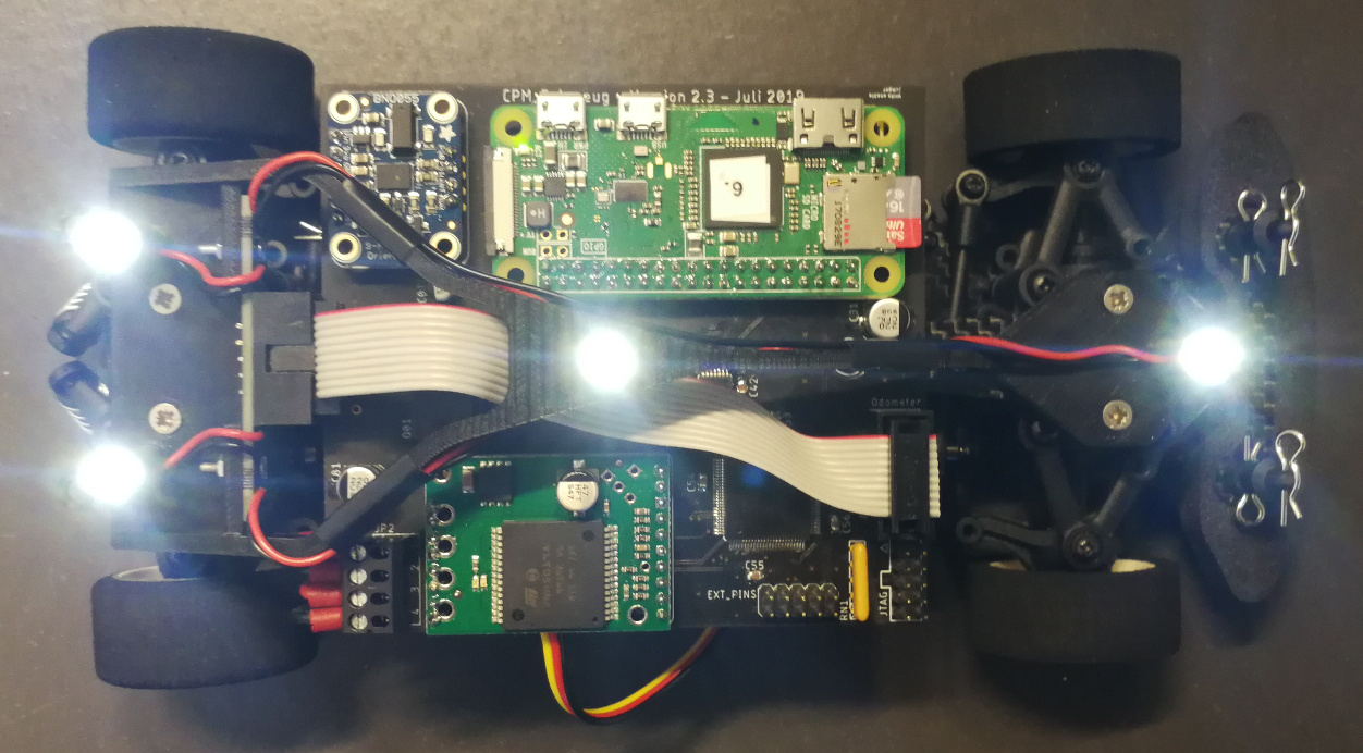
Other light sources and reflective surfaces on the vehicle can create false signals and must be covered with tape. This includes the connectors on the Raspberry Pi and the status LEDs on the motor speed controller.
Vehicle Pose
The outer three LEDs indicate the vehicle pose and are permanently illuminated. The section Pose Calibration describes how the LED positions are related to the reference pose.
...
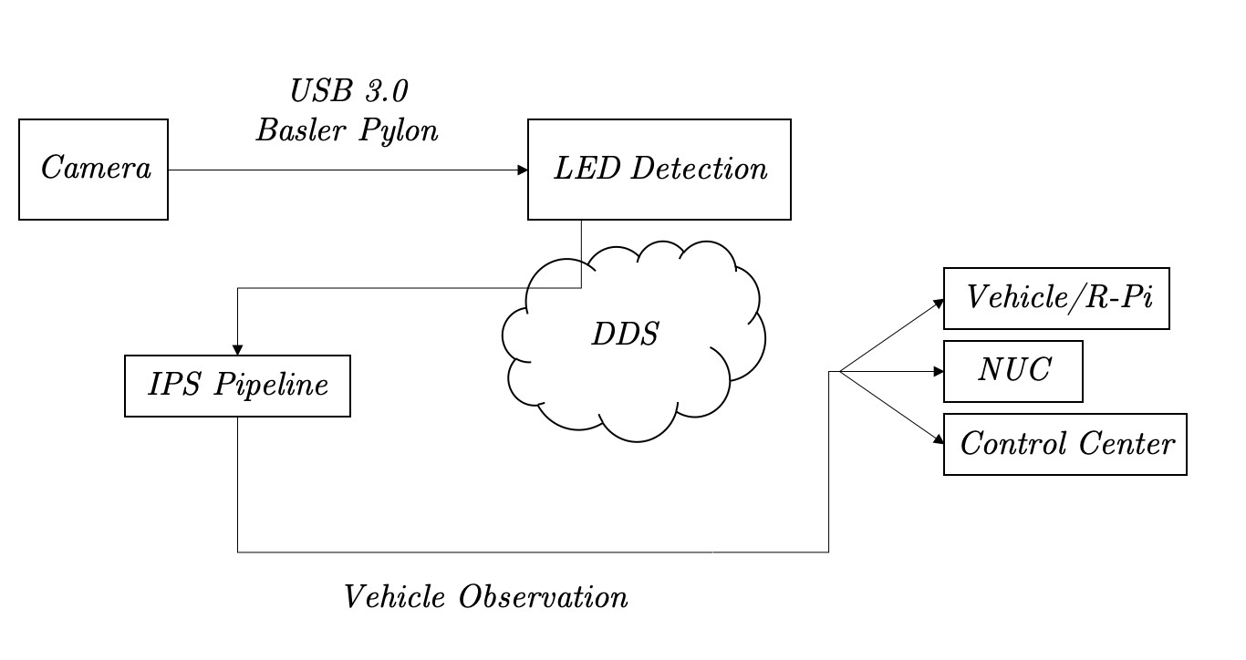
The IPS software has two major components, the LED detection and the IPS pipeline. The LED detection reads images from the camera at 50 Hz and extracts the list of image coordinates for all visible LEDs. These LedPoints are published via DDS. The raw images are not saved or published, as this would create impractically large data volumes. The IPS pipeline processes the LED points and publishes VehicleObservations, which include the vehicle's position, orientation, identity and a timestamp.
LED Detection
The LED detection uses the OpenCV functions cv::threshold, cv::findContours and cv::moments to find the centers of the LEDs.
...
The IPS pipeline performs a relatively complex data processing task. To make the software easier to understand, it is broken down into independent, stateless processing steps.
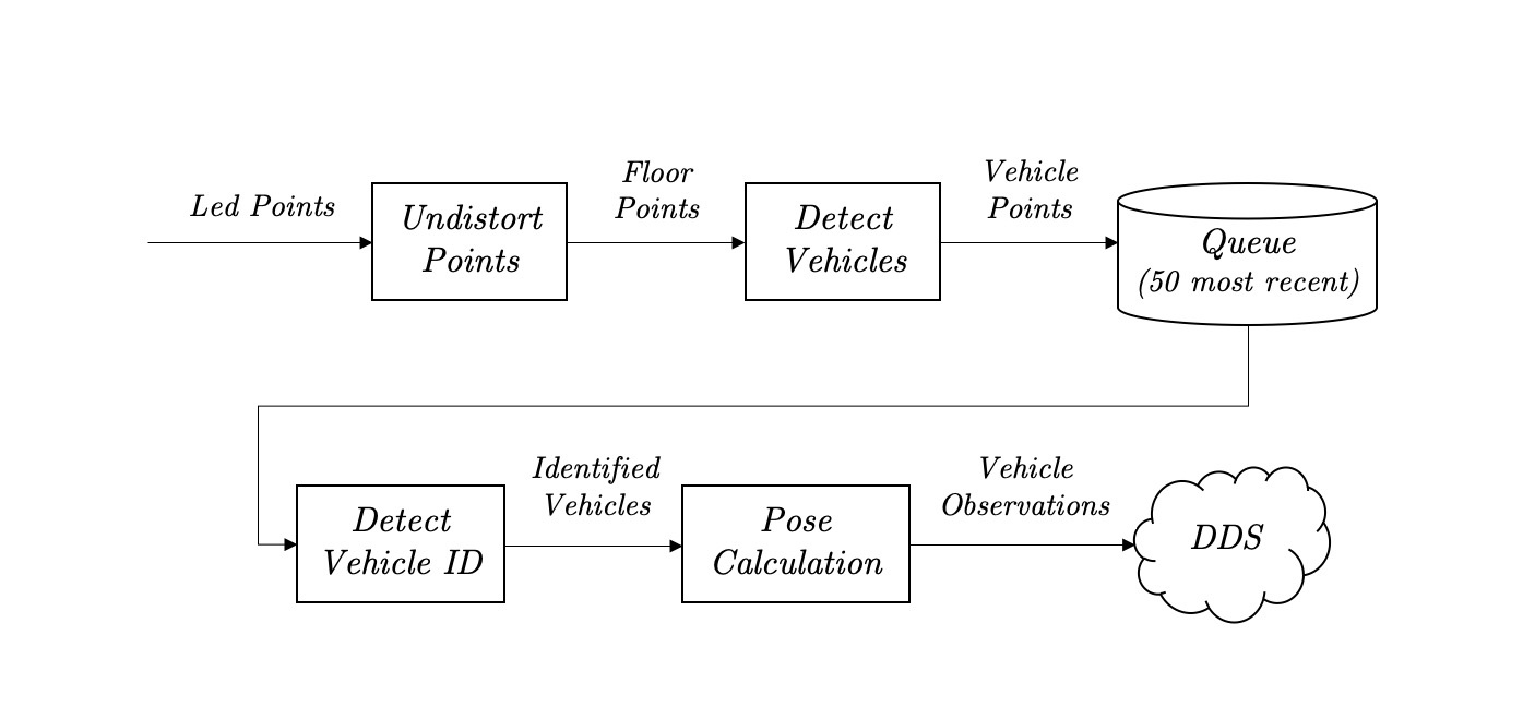
The UndistortPoints function transforms the image/pixel coordinates to metric coordinates on the driving surface (floor). The calculation is based on a calibration image. See https://github.com/embedded-software-laboratory/cpm-lab/tree/master/matlab_scripts/camera_calibration
...
...
...
Pose Calibration
The vehicle pose has the format (x, y, yaw). The yaw is the rotation angle in radians of the vehicle around the vertical axis in the counter-clockwise direction. When yaw=0, the vehicle points in the x-direction. The coordinates (x, y) give the location of the vehicle's reference point. The reference point is defined as the geometric center between the front and rear axle.
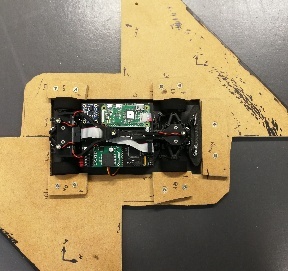
To accurately implement this definition of the pose, another measurement and calibration procedure is performed. First we need a means of accurately placing the vehicle on the floor, such that the true pose is known. The vehicle is clamped into a piece of wood, which extends the vehicle's local x/y coordinate system. This makes it simple to manually align the vehicle with the checkerboard pattern.
While the IPS is running, the vehicle is placed in various poses on the floor, following a particular calibration sequence. The calibration features (back_x, back_y, direction_x, direction_y) are recorded from the running IPS. A linear calibration is then fitted using least squares.
Overview
Content Tools