Page History
...
- Current Firmware: https://github.com/embedded-software-laboratory/cpm_lab/tree/master/low_level_controller
For questions, please contact Patrick Scheffe
| Info |
|---|
Steps require Main Vehicle PCB to be connected to vehicle to provide power |
For questions, please contact:
...
1. Atmel Studio 7.0
- Start Atmel Studio 7.0
...
- Load current vehicle firmware solution "vehicle_atmega2560_firmware.atsln"
2. ICE Programmer
| Warning |
|---|
Make sure vehicle is powered off before connecting the programmer! |
- Check pinout of Programmer, Vehicle and Connector Cable:
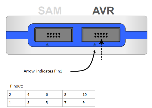
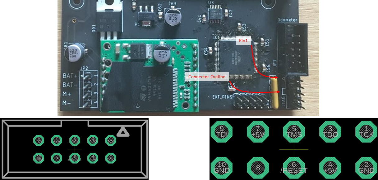
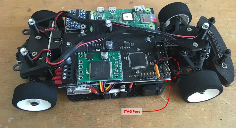
- With vehicle power OFF, connect ICE programmer AVR Port to JTAG header.
Make sure to check pinout of Programmer, Vehicle and Connector Cable:
...
- Connect ICE programmer with USB cable to PC.
3. Fuses
- Turn ON vehicle
...
- Connect to ATmega Chip
...
- with Tools→Device Programming
- Click Apply
- Click Read
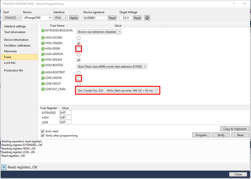
- Set the correct fuses (see table and screenshot below)
- Click Program
| Fuse | Correct Setting |
|---|---|
| HIGH.SPIEN | Unchecked |
| HIGH.EESAVE | Optional i.e. checked or unchecked |
| LOW.CKDIV8 | Unchecked |
| LOW.SUT_CKSEL | Ext. Crystal Osc. 8.0- MHz; Start-up time: 16 CK + 65ms |
| Warninginfo |
|---|
If vehicle is behaving irregularly i.e. servo steering is acting erratic, LEDs timing appears off, this is most likely due to an issue with the clock.
|
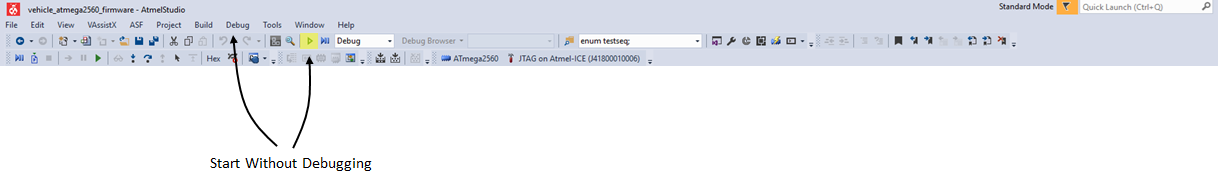
4. Flash ATmega
- Flash chip using Start without Debugging
...
- Turn OFF vehicle
...
- Disconnect programmer
5. Tests
By setting a jumper, a test mode is activated. This allows testing the inputs and outputs without the MLC.
...
Overview
Content Tools