Page History
...
The program is based on the routing graph for the map layout.
Sources:
C++
MATLAB
https://github.com/embedded-software-laboratory/cpm_lab/blob/master/tools/map_print/map_print2/lane_graph.mThe original lane graph is defined as followed:
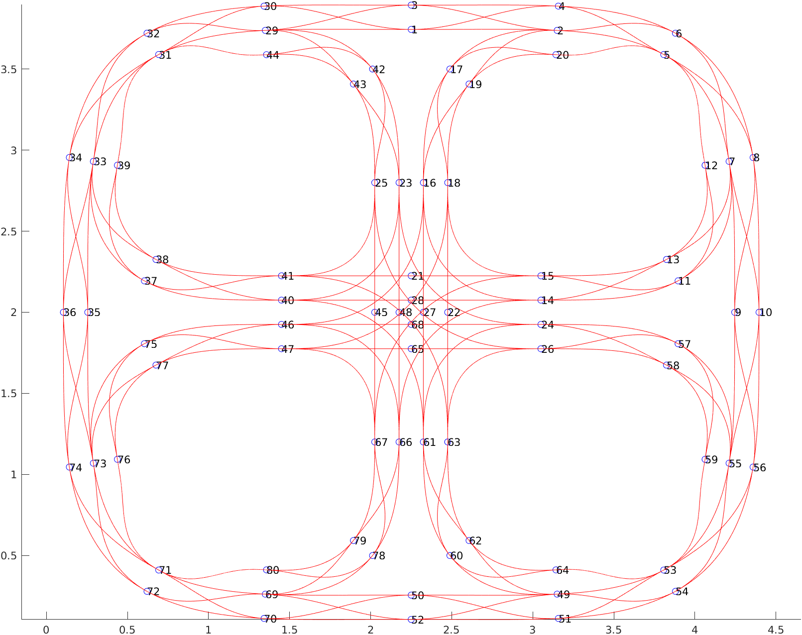
Each node represents the index in the lane graph to receive the information you need for your trajectory:
struct LaneGraph{

vector node_x;
vector node_y;
vector nodes_cos;
vector nodes_sin;
vector edges_start_index;
vector edges_end_index;
vector edges_x;
vector edges_y;
vector edges_sin;
vector edges_cos;
}
The graph edges correspond to center lines, along which a vehicle may drive. Parallel lanes are not modeled, instead extra edges are added for lane changes in discrete locations. All values from your lane graph are already included in the struct which you find in:
You can modify this lane graph by using the programs written in Matlab and can be found in:
Tools include: adding edges, deleting edges, deleting points and selecting points.
Preparation I : Write a class "LaneGraphTools"
...
Overview
Content Tools