Page History
| Anchor | ||||
|---|---|---|---|---|
|
| Table of Contents | ||||
|---|---|---|---|---|
|
| Info |
|---|
These instructions do not include PCB soldering. For instructions on PCB assemly, see PCB Assembly. |
For questions regarding assembly, please contact:
- Patrick Scheffe
0. Bill of Materials
The following tables show the quantities of the components needed for one vehicle. Note: The elements needed for PCB-Assembly are not given here.
| Mechanical Components | Quantity | |
|---|---|---|
XRAY M18 Pro LiPo Kit | 1 | |
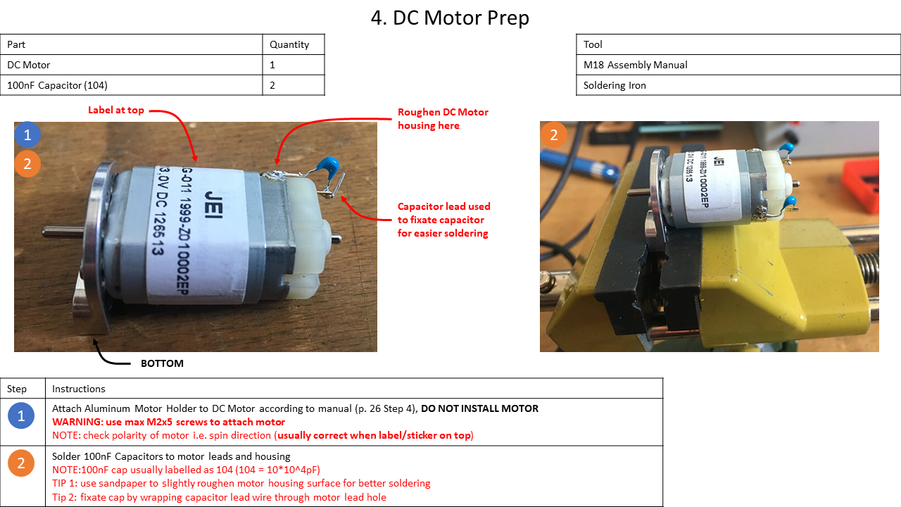
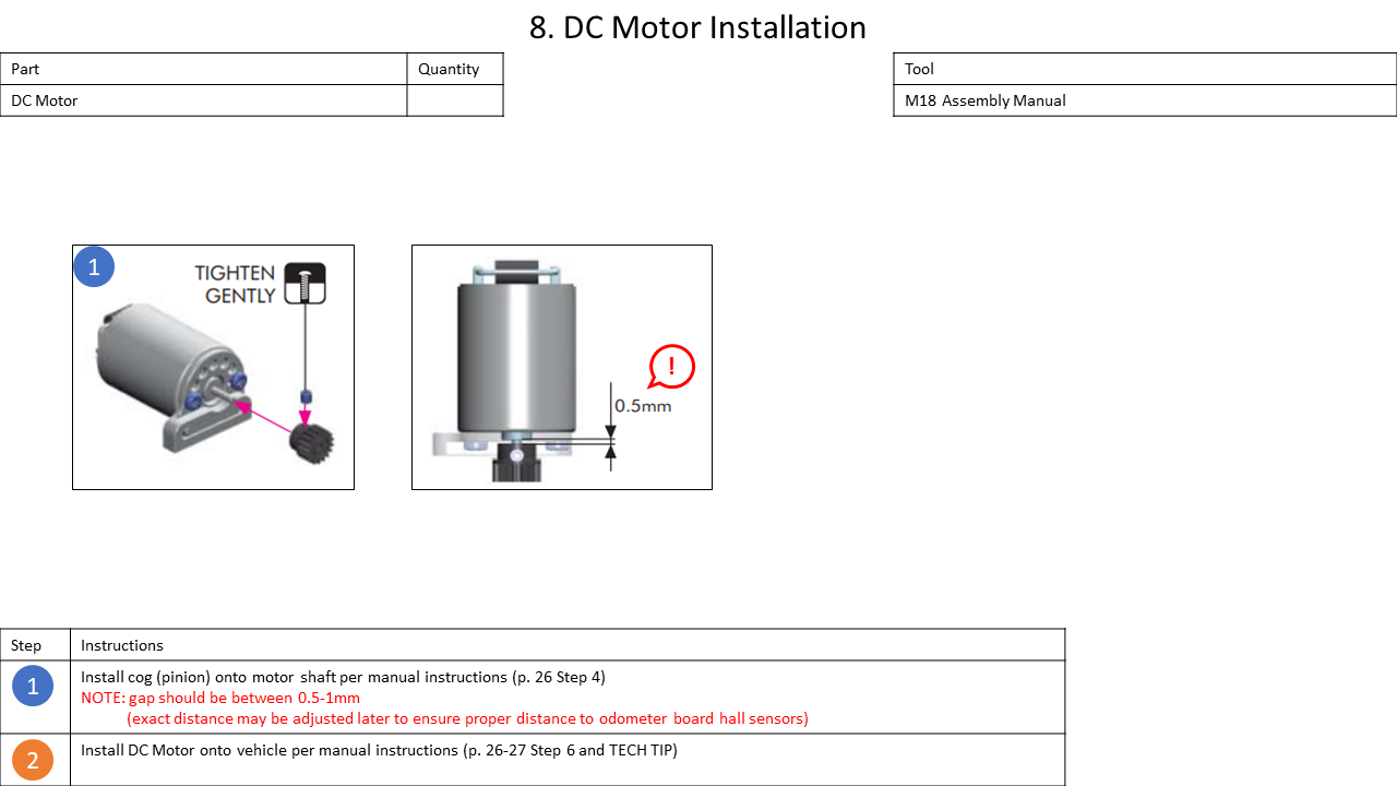
NF113LG-011 DC motor | 1 | |
Motor Magnet | 1 | |
| 1 | ||
| 1 | ||
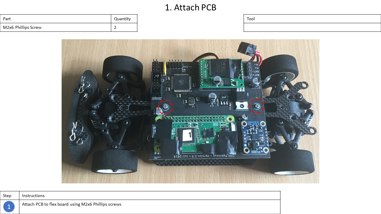
Screws | M2x6mm | 2 |
M2x5mm | 2 | |
M2x10mm Countersink | 2 | |
M2.5x6mm | 3 | |
| M3x10mm | 2 | |
Nuts | M2 | 6 |
| M2.5 | 5 | |
| M3 | 4 | |
Washers | M2.5 | 2 |
inner diameter: 2.2mm | 2 | |
| Electrical Components | Quantity | ||
|---|---|---|---|
| Vehicle Main Board | 1 | ||
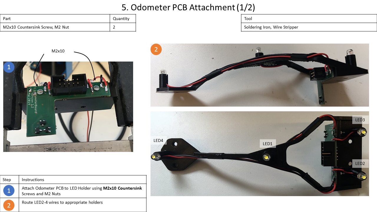
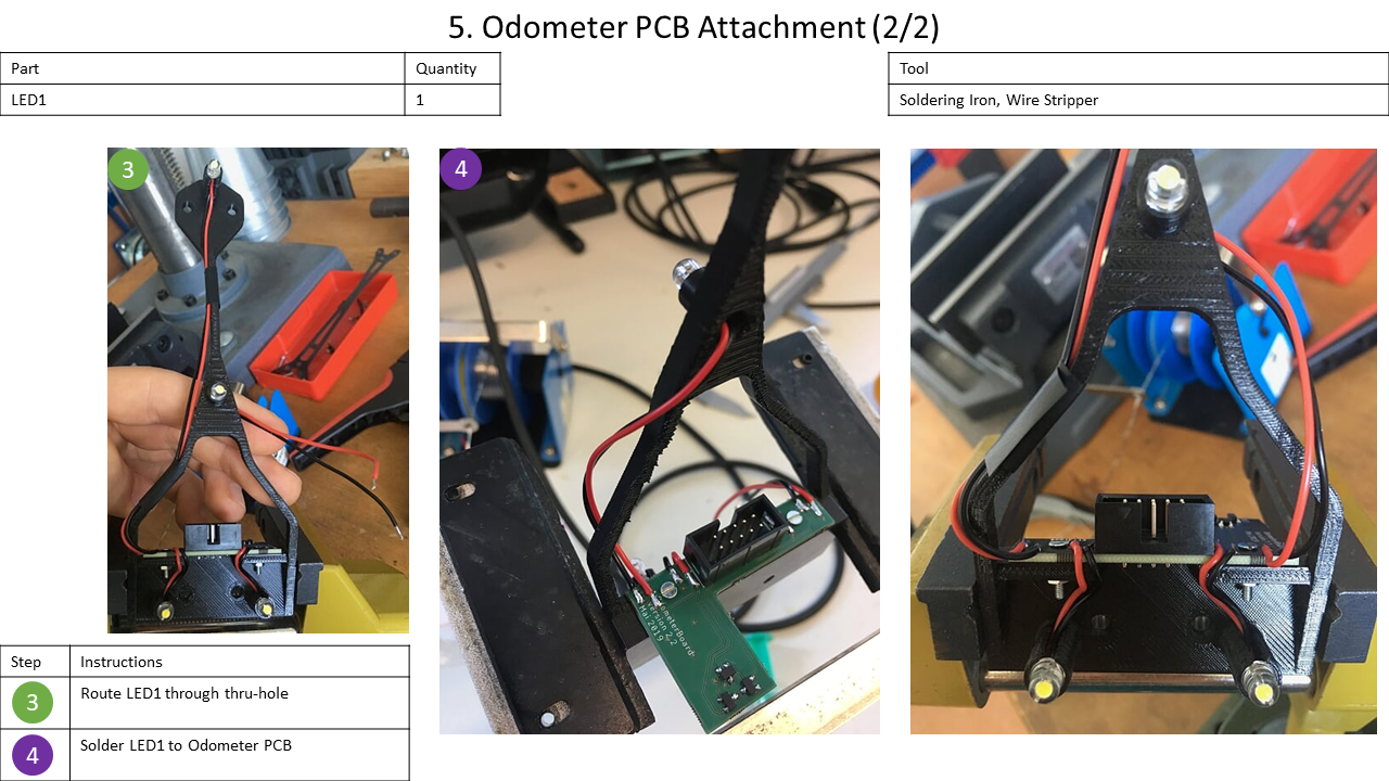
| Odometer Board | 1 | ||
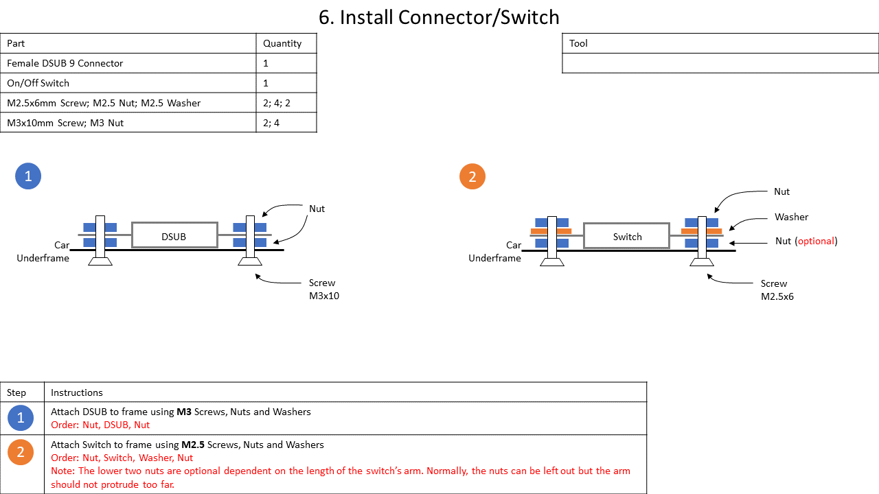
Female DSUB 9 connector | 1 | ||
HiTEC D89MW servo | 1 | ||
Banana connector 4mm | 2 | ||
Banana connector 2mm | 1 | ||
100nF capacitor | 2 | ||
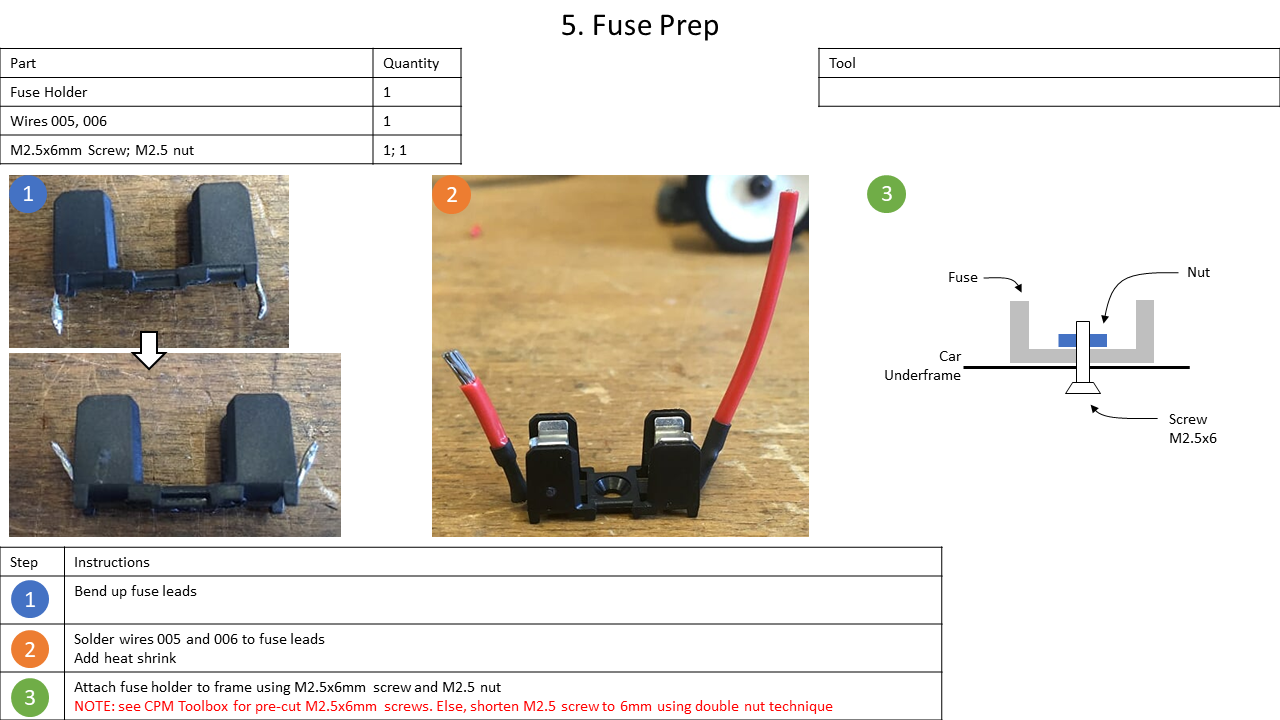
Fuse holder 0031.8201.G | 1 | ||
Fuse 521,027 | 1 | ||
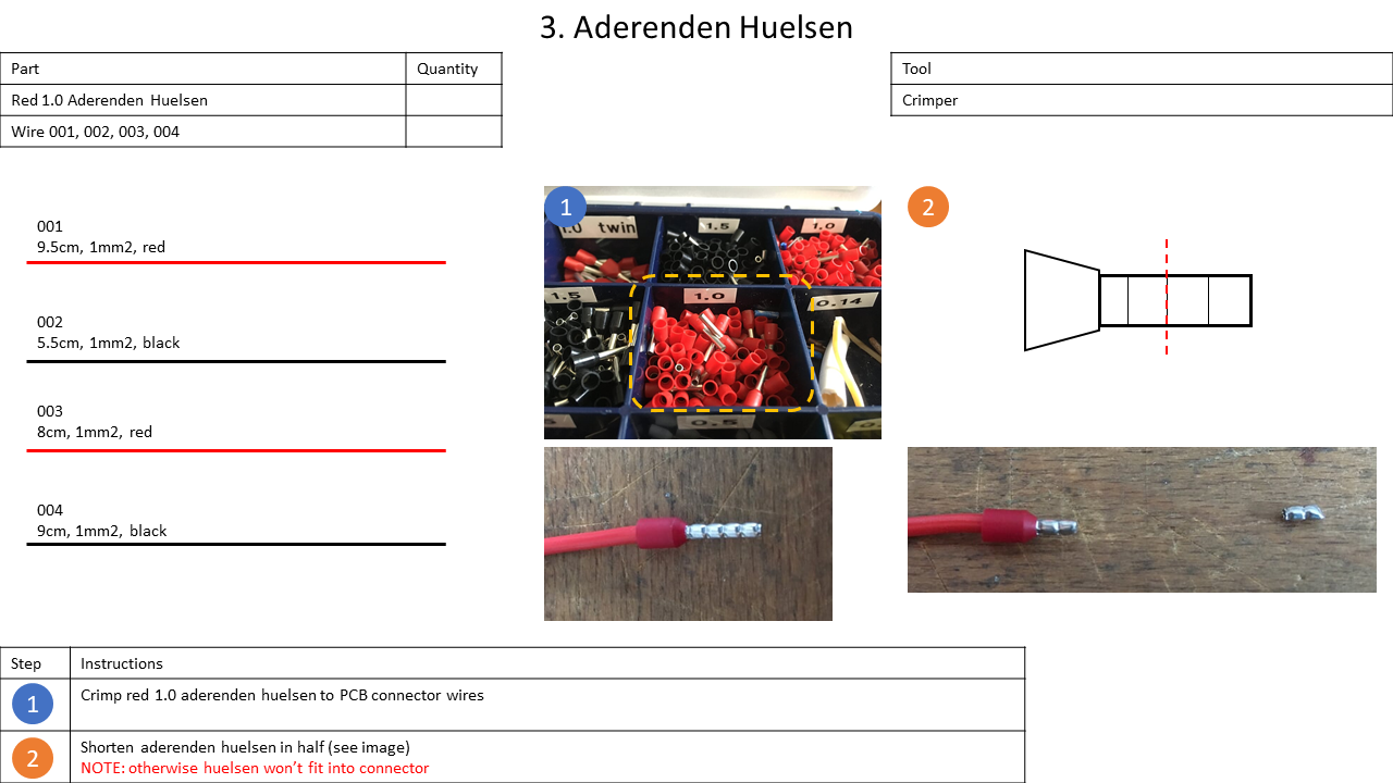
Red 1.0 wire end ferrule | 4 | ||
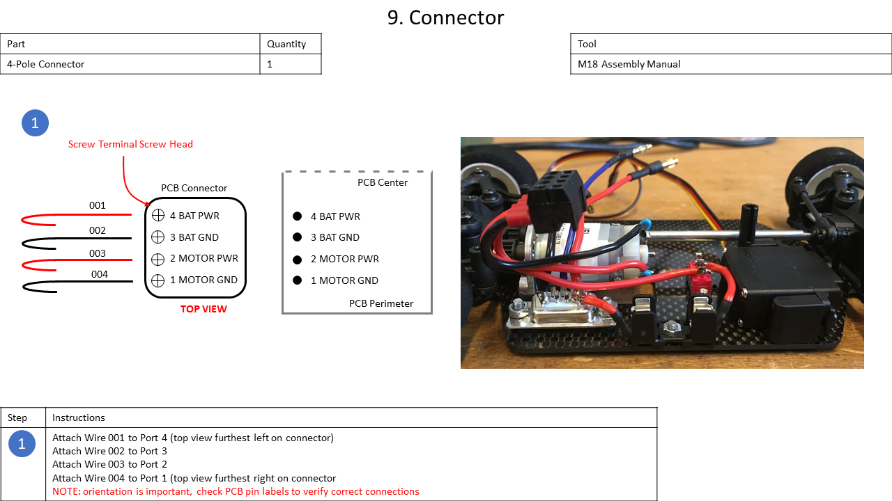
4-Pole connector | 1 | ||
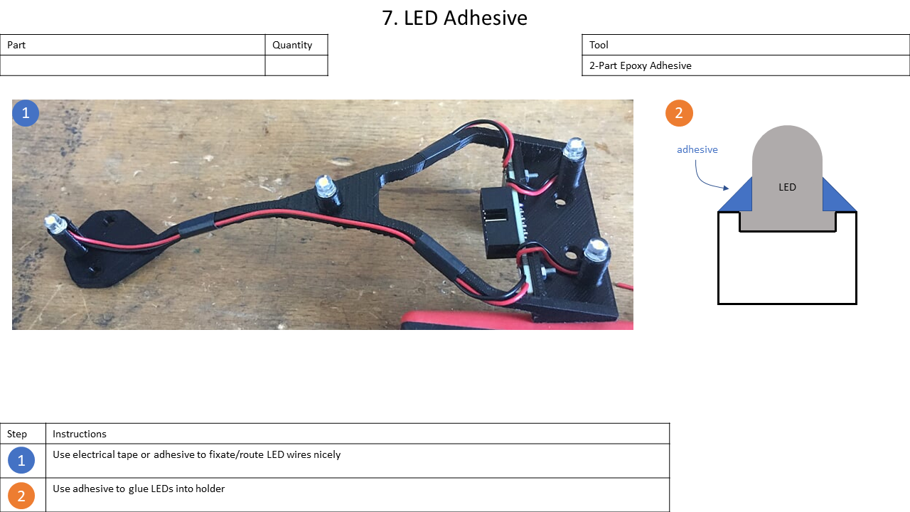
LED NSDW570GS-K1 | 4 | ||
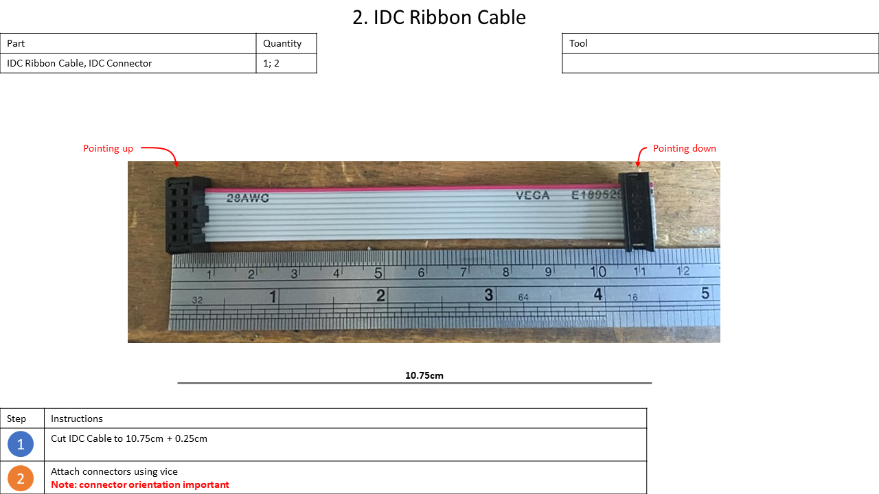
IDC Ribbon cable 10 POL (AWG 28-10G 10M) | 11 cm | ||
IDC Socket 10 POL | 2 | ||
Heat shrinks | |||
Silver wire | |||
Color | Gauge | ||
Wires | Red | 1mm2 | 31 cm |
Black | 1mm2 | 25.5 cm | |
Blue | 0.5mm2 | 8.2 cm | |
Red | 0.14mm2 | 35 cm | |
Black | 0.14mm2 | 35 cm | |
| Tools |
|---|
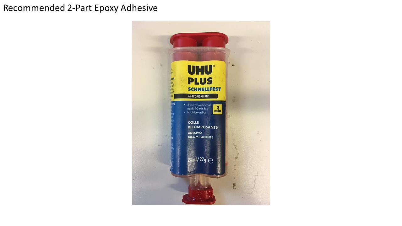
2-Part epoxy adhesive |
HiTEC DPC-11 Software |
Servo Programmer incl. necessary harnesses |
Soldering iron |
Crimper |
3D-Printer |
Diverse drills, screwdrivers and allen keys |
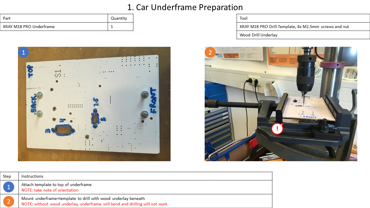
1. Underframe Preparation
The CPM Lab's vehicles are based on the XRAY M18 Pro LiPo Kit. However, for using it in the Lab, several adaptations have to be applied to it.
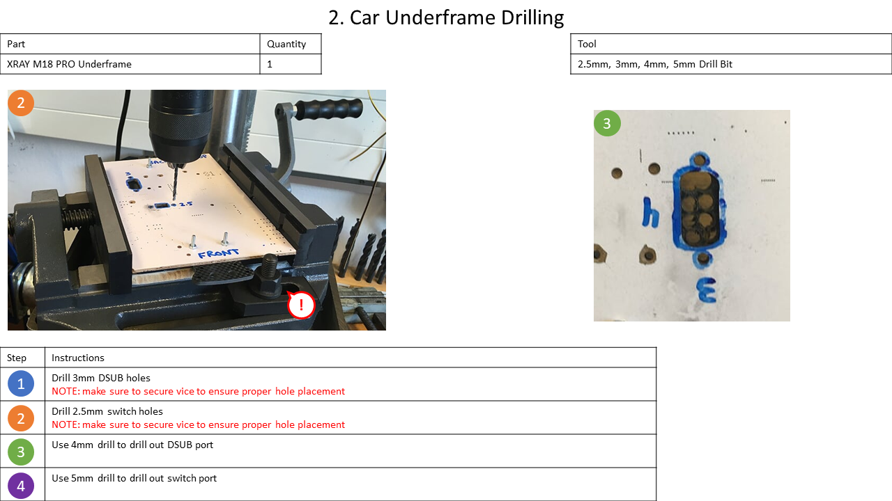
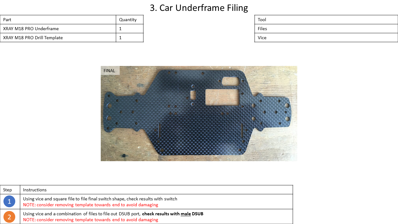
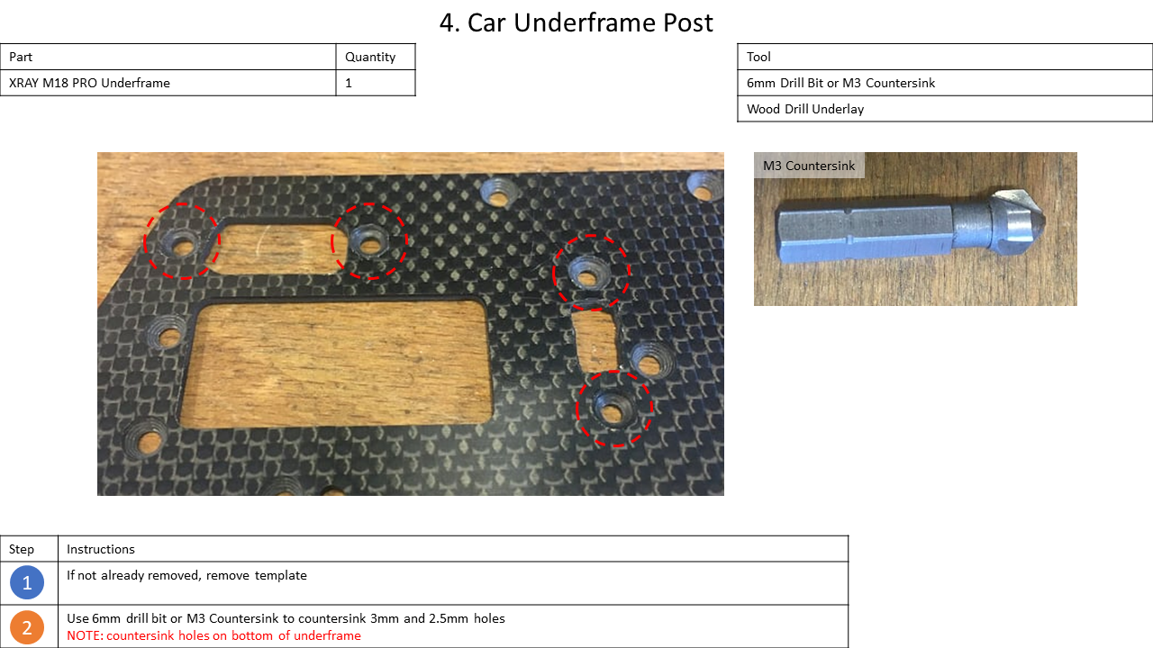
In this step, additional holes will be added to the underframe of the M18 to provide mounts for the charging connection, the fuse, and the switch. For this, a wooden template is used onto which even multiple underframes can be attached.
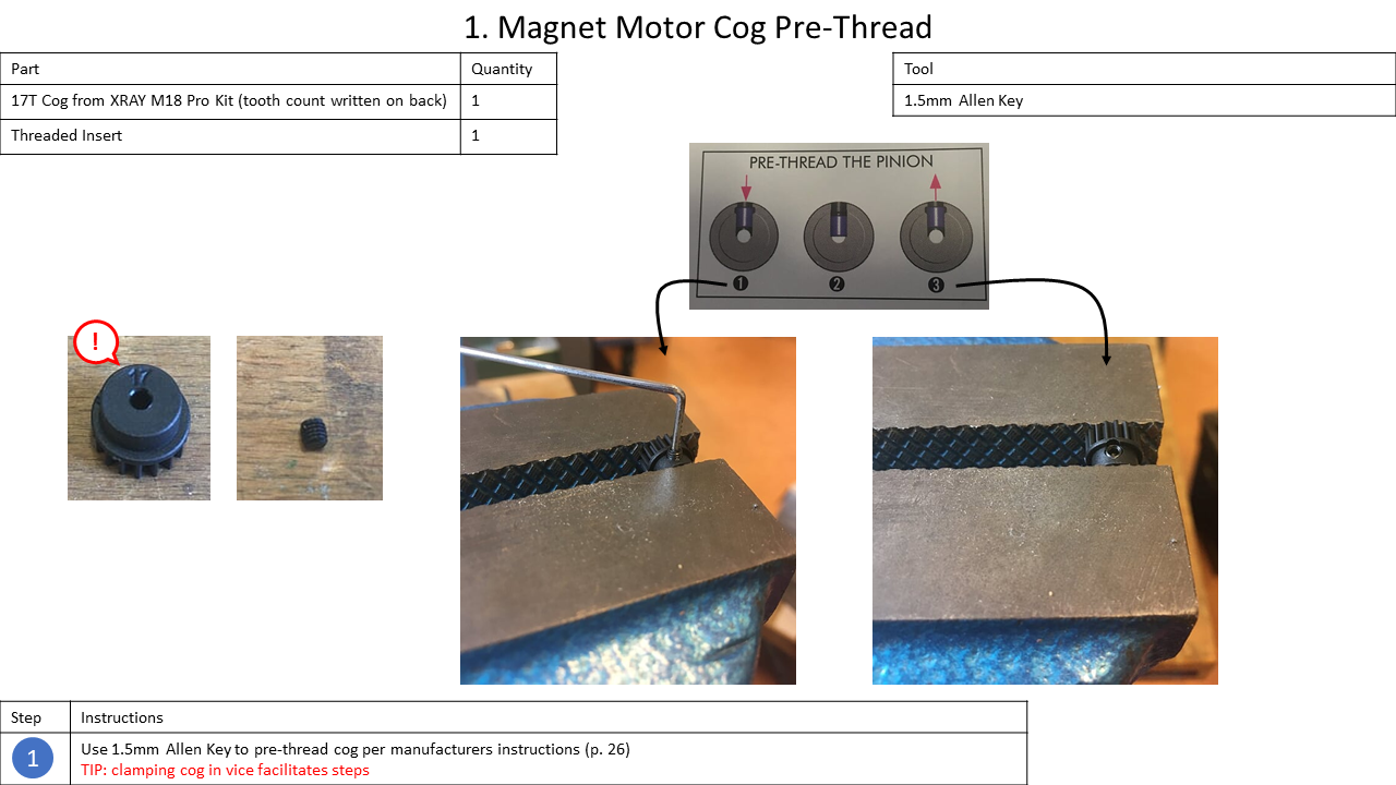
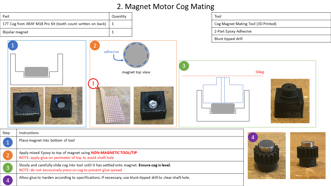
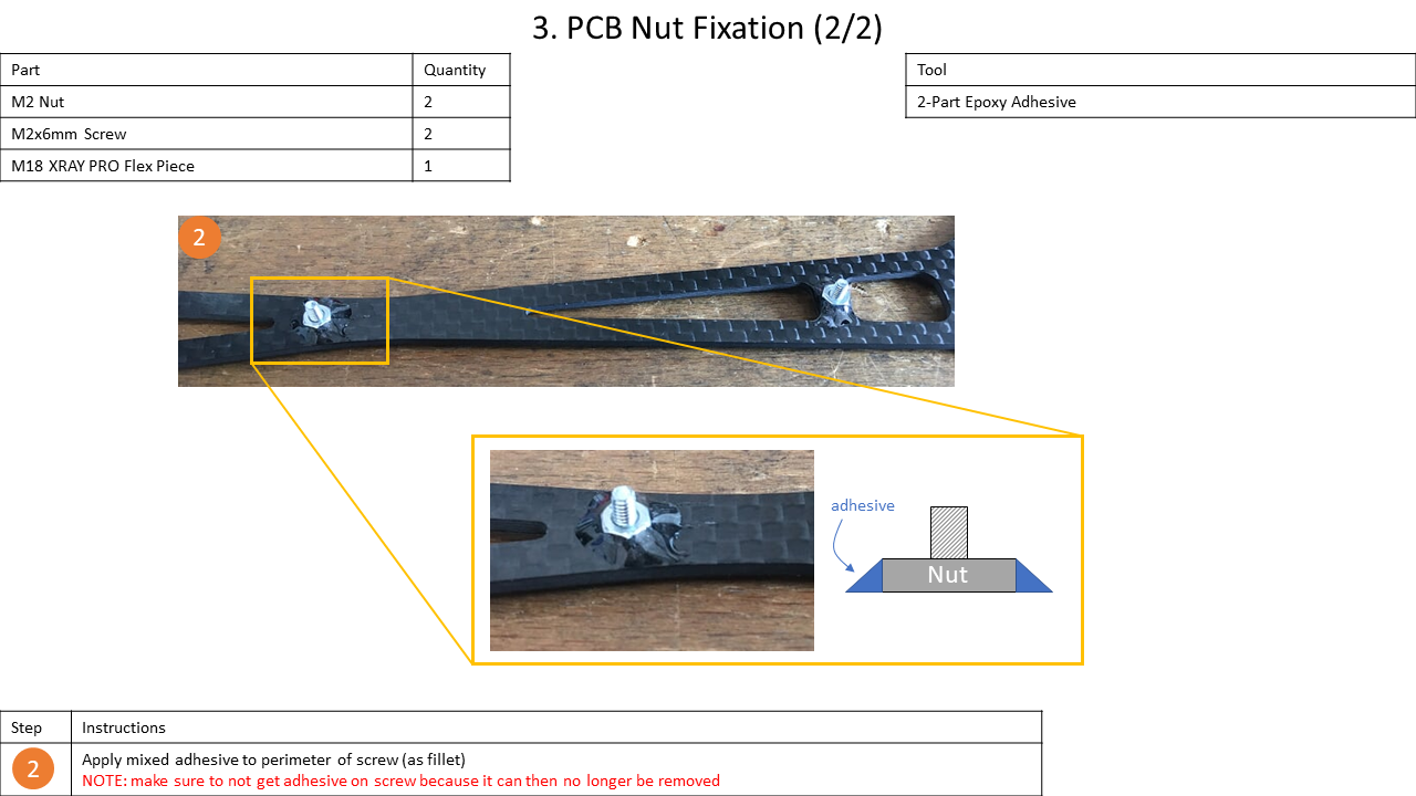
2. Adhesive Preparation
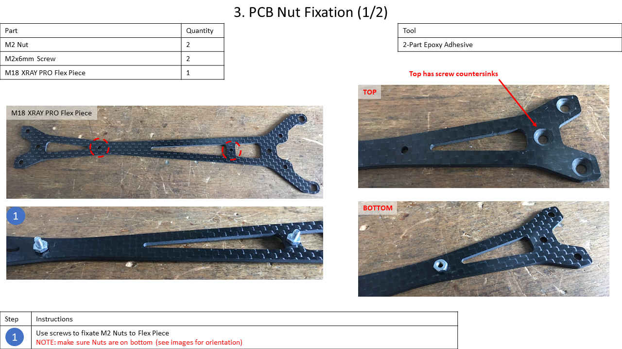
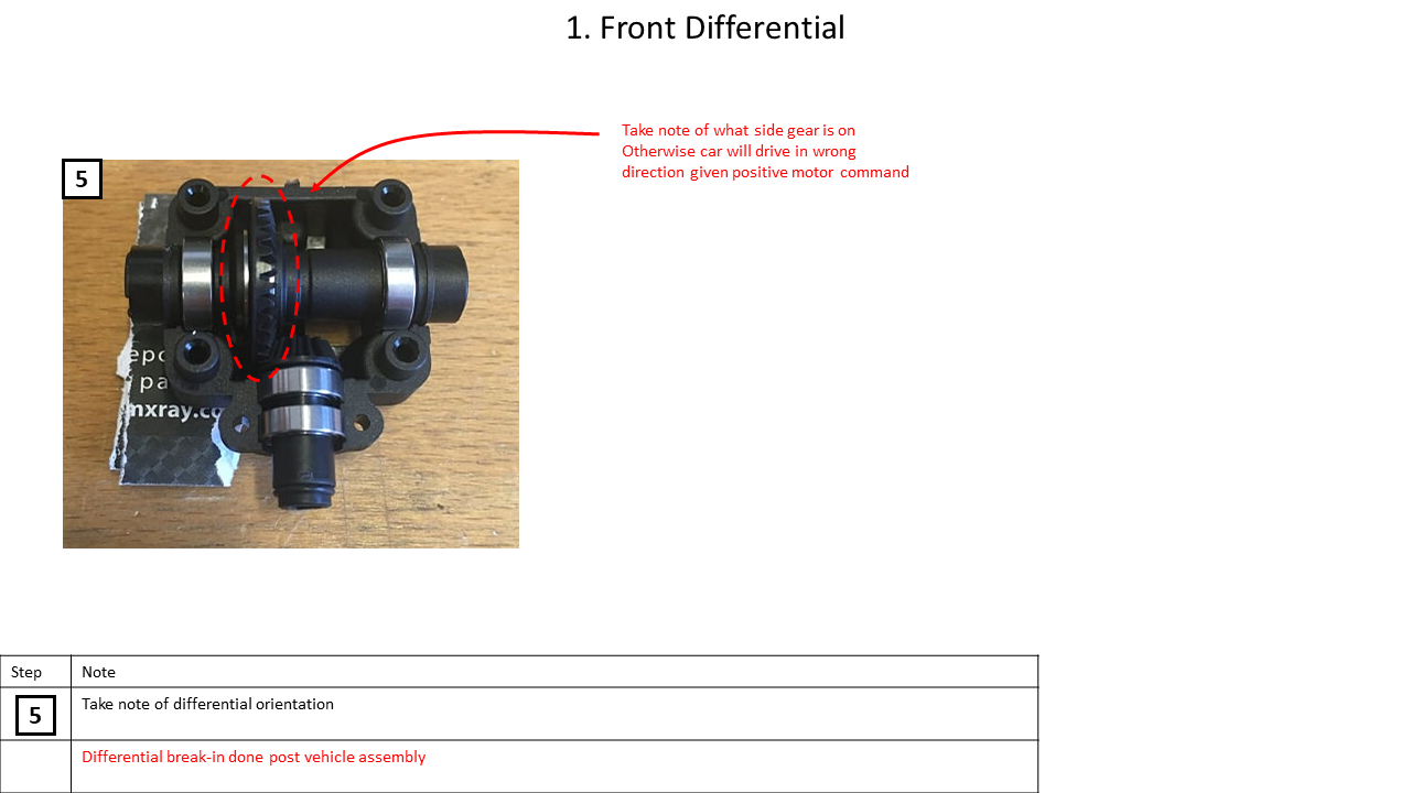
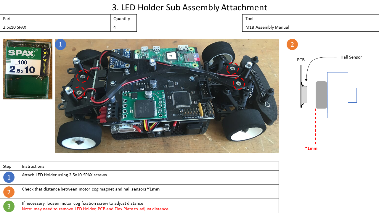
Since the adhesive needs some time for drying, this step is done now. On the one hand, the magnet must be adhered to the cog to allow distance measuring by the odometer. On the other hand, two nuts fixed to the Flex Piece will allow an easier fastening of the Main Board in the end.
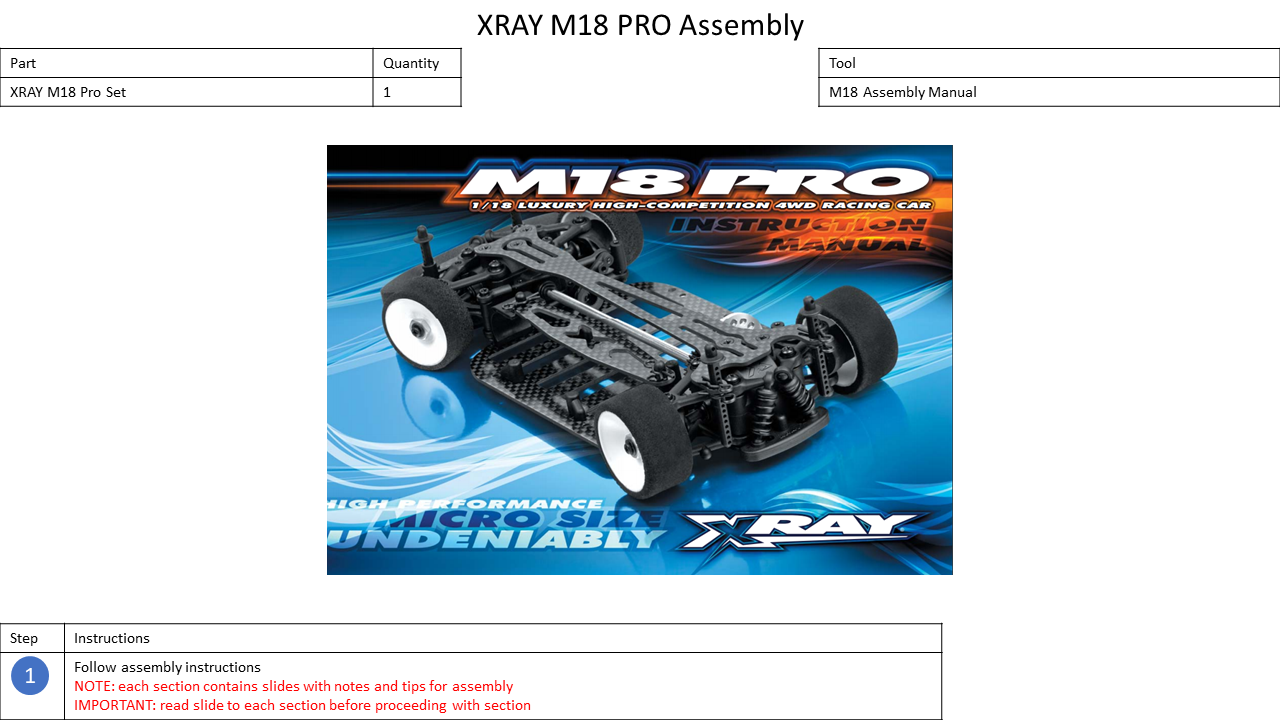
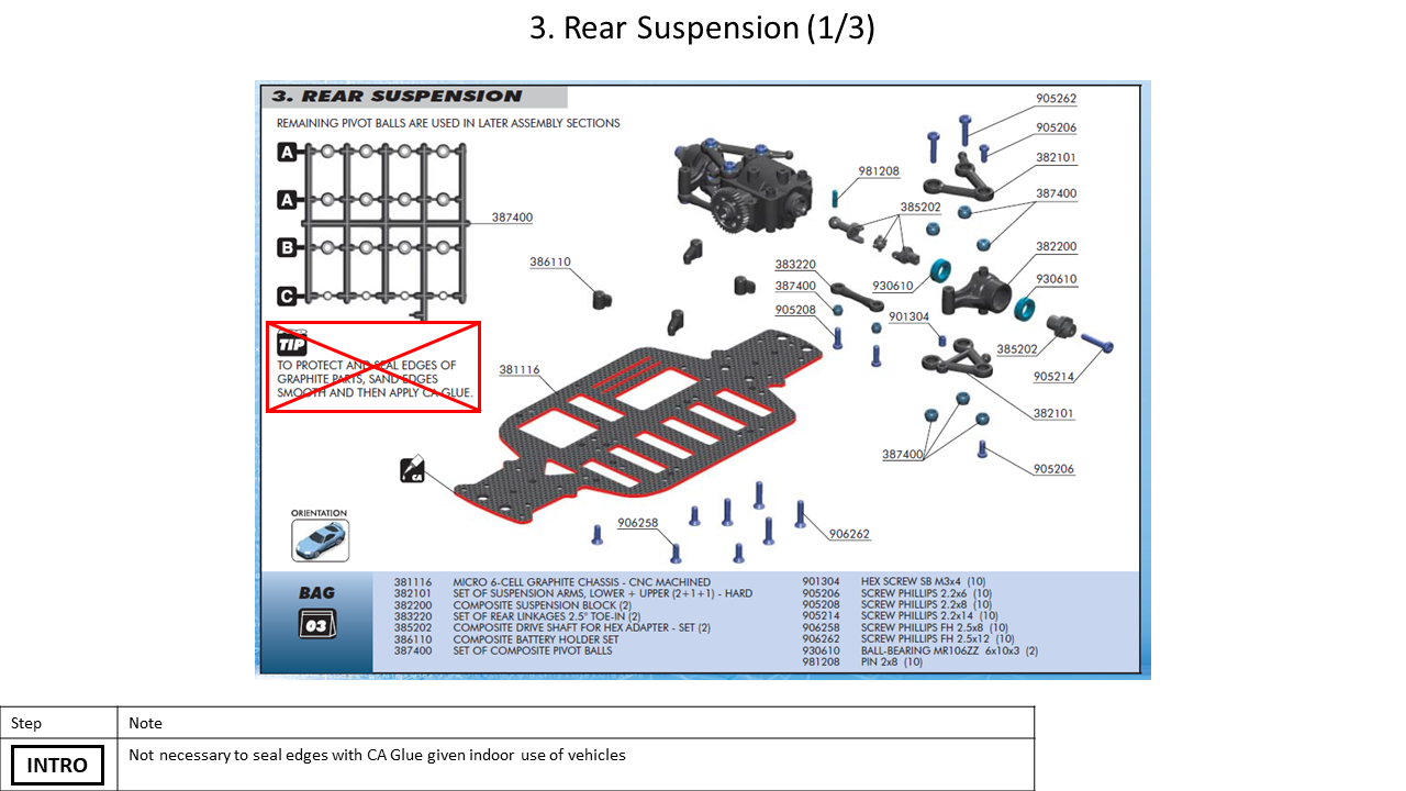
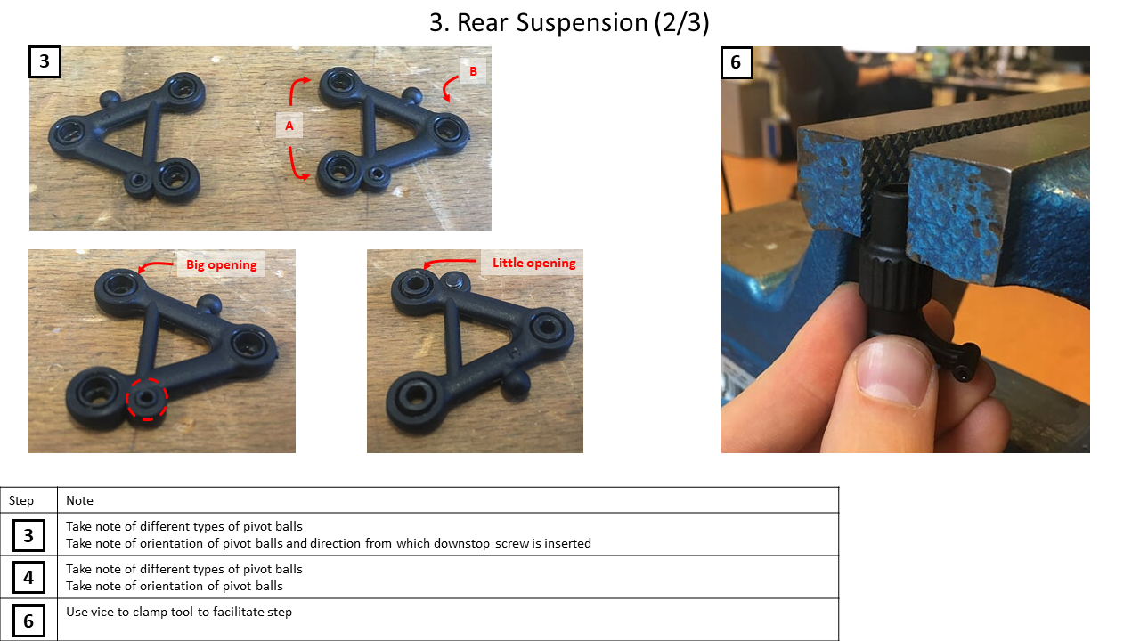
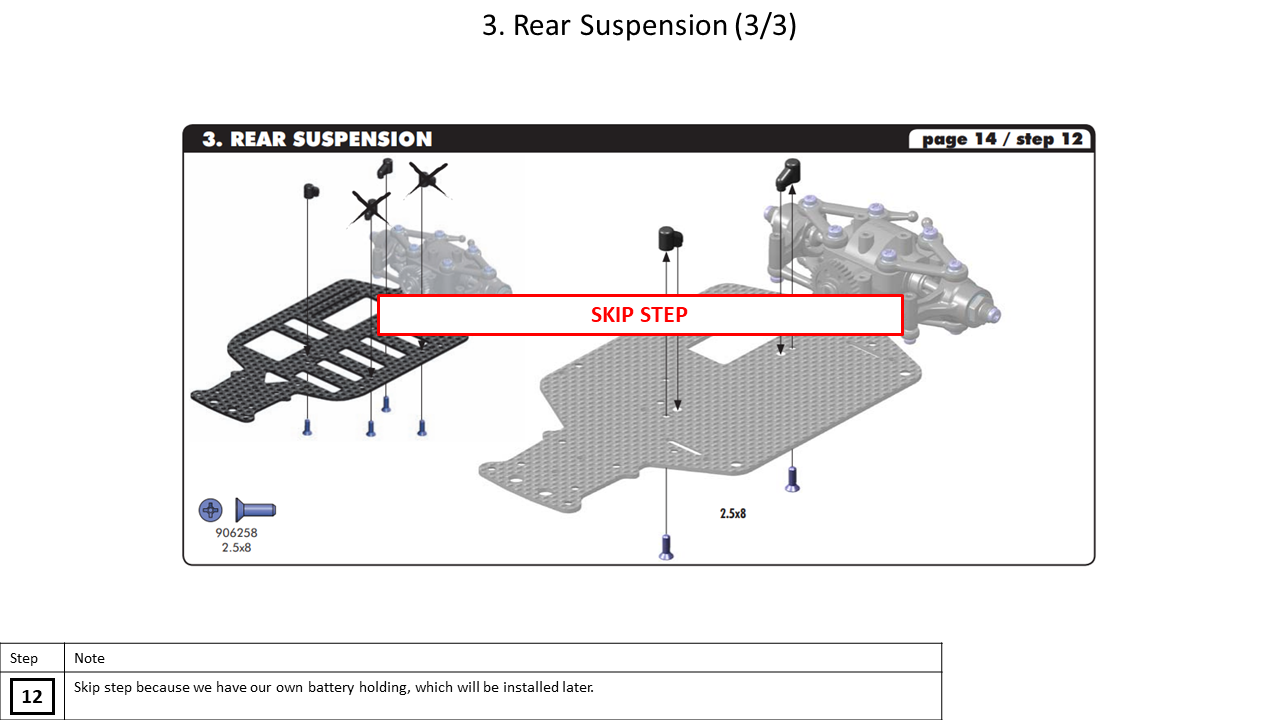
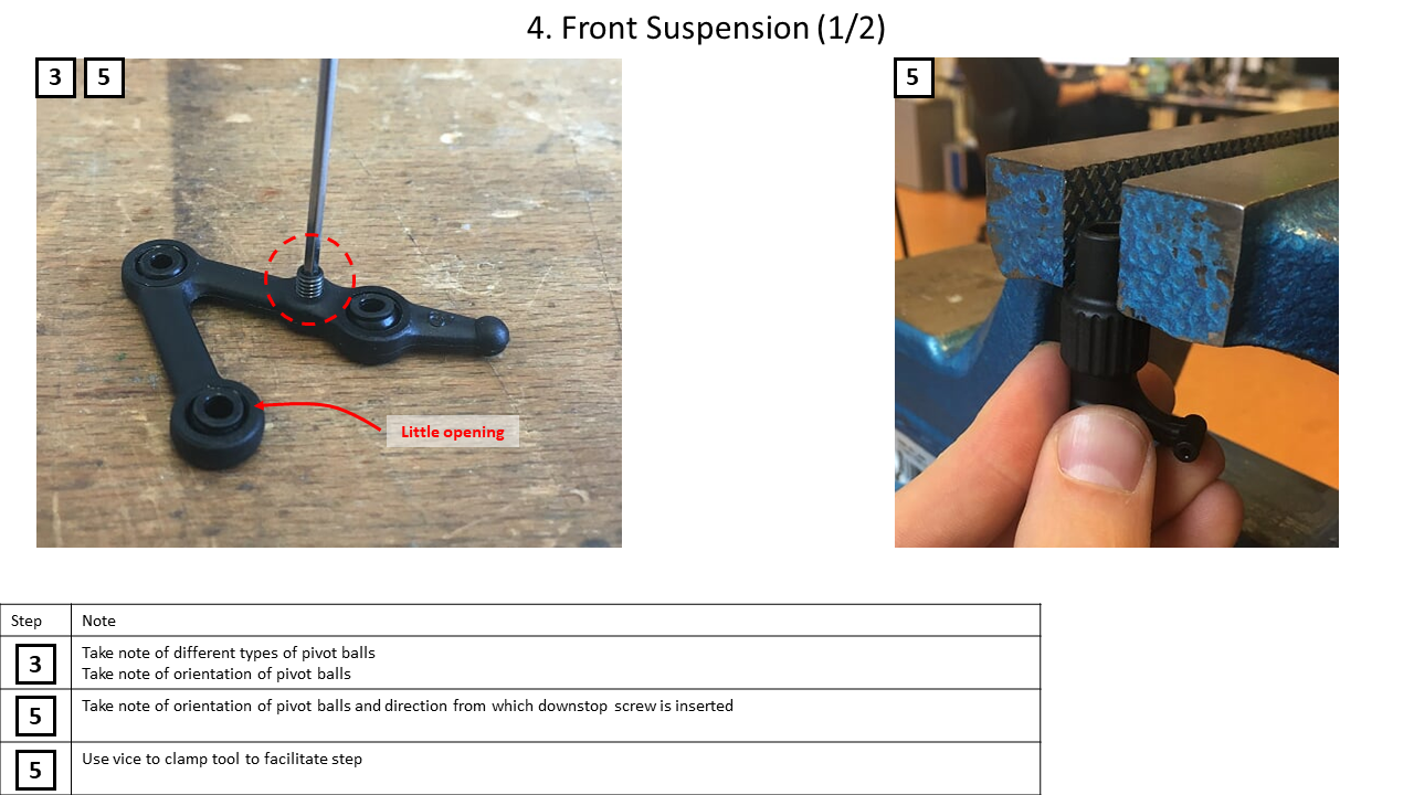
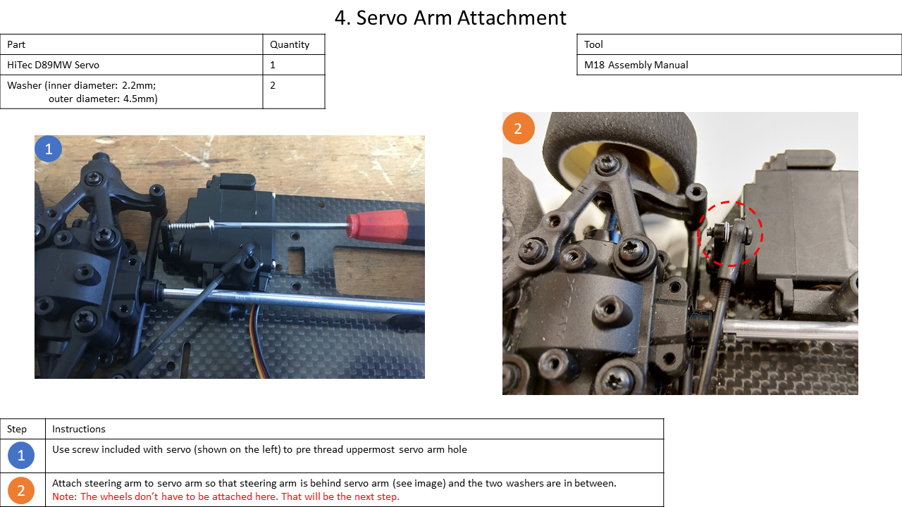
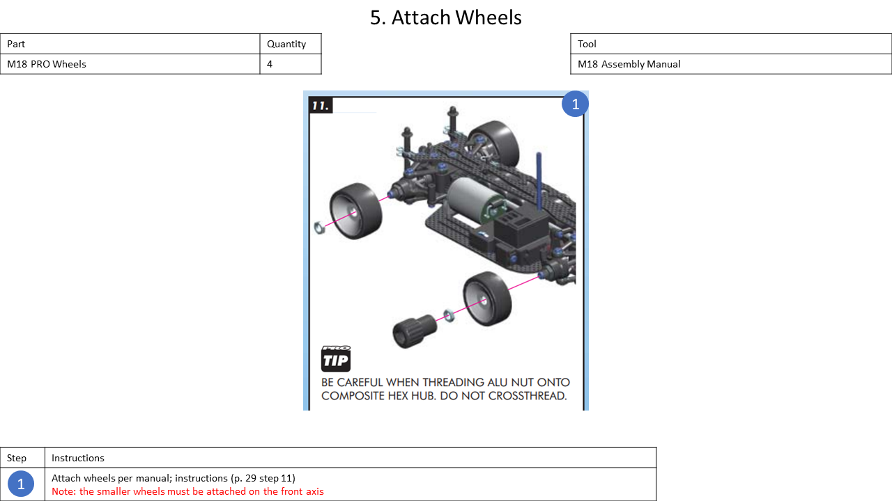
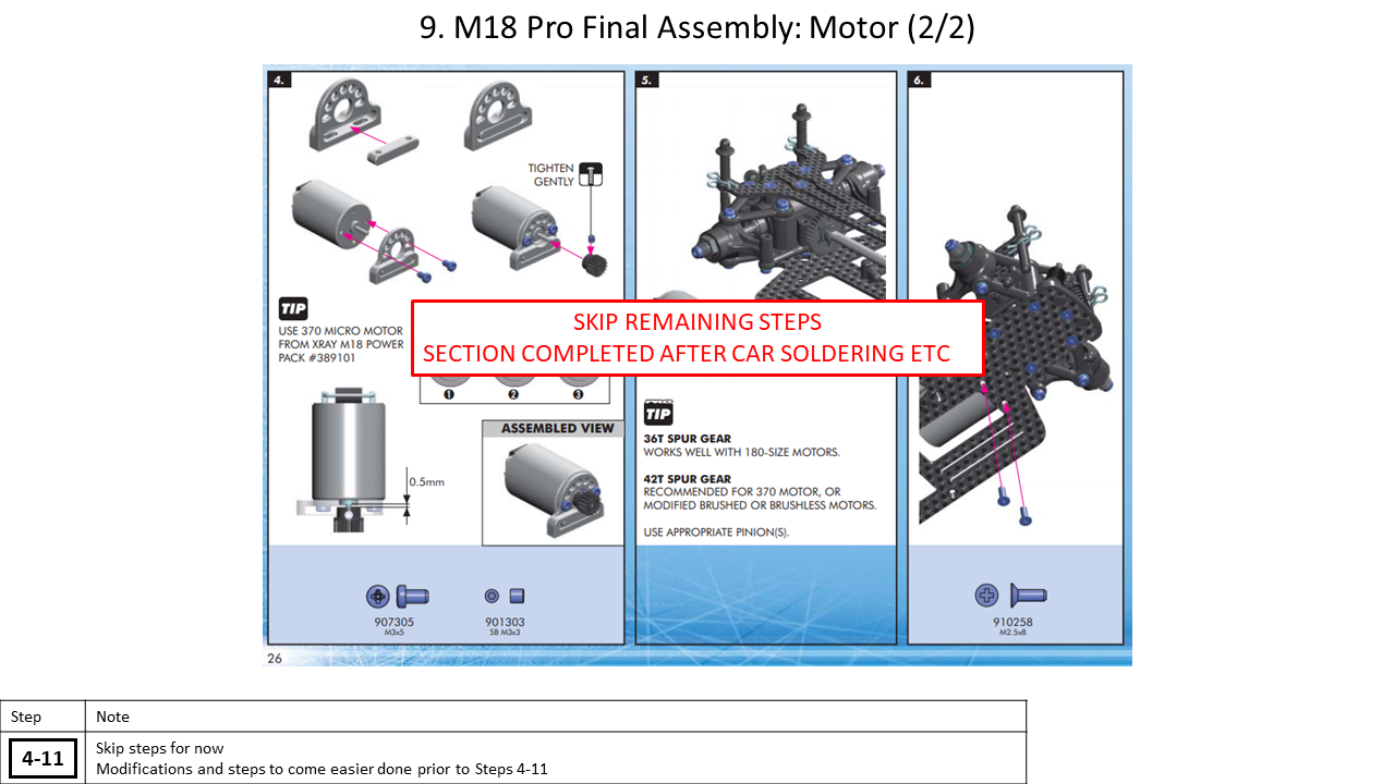
3. XRAY M18 PRO Assembly
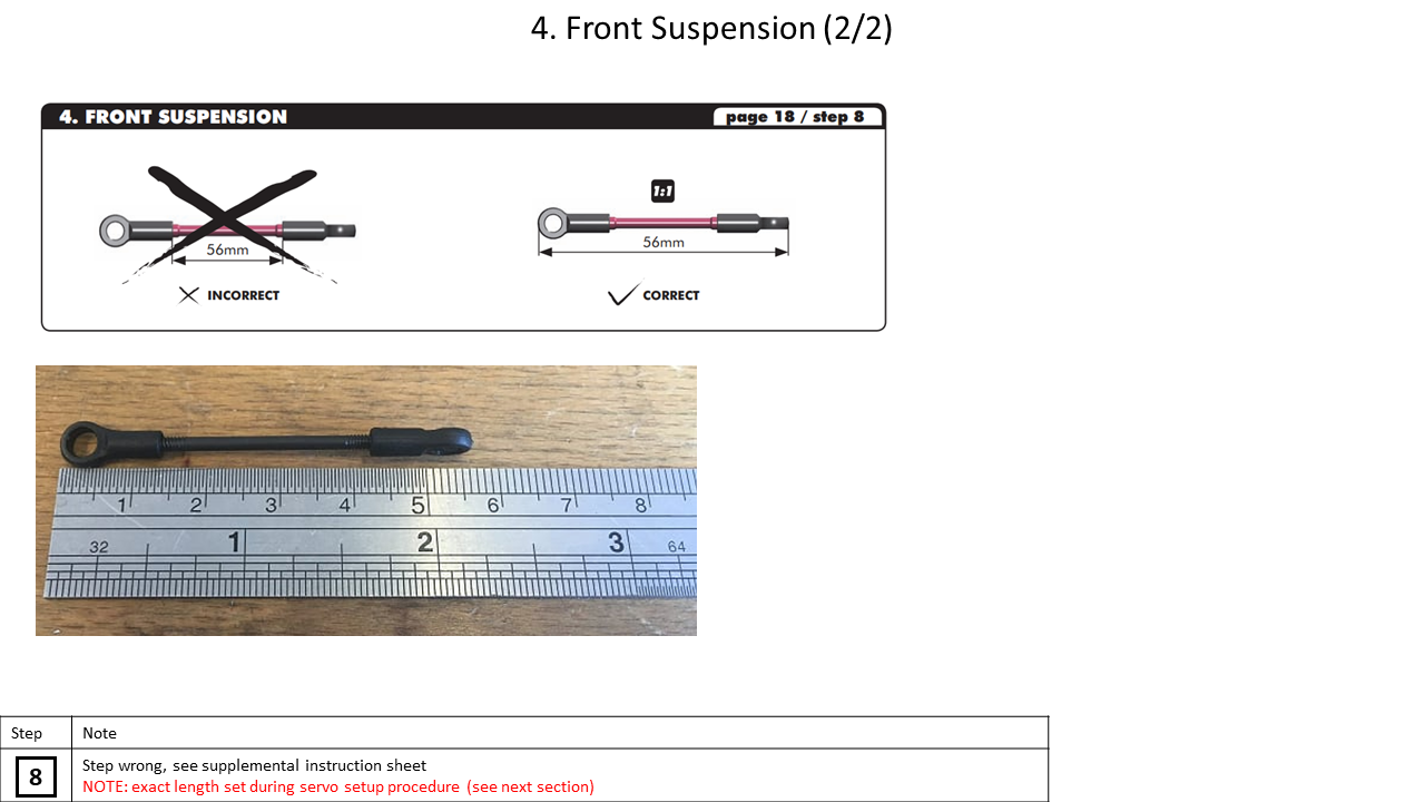
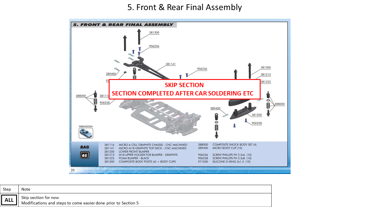
In the next part, the M18 Pro is built according to its manual, mostly. Consequently, this section focuses on tips and indicates deviations from the original.
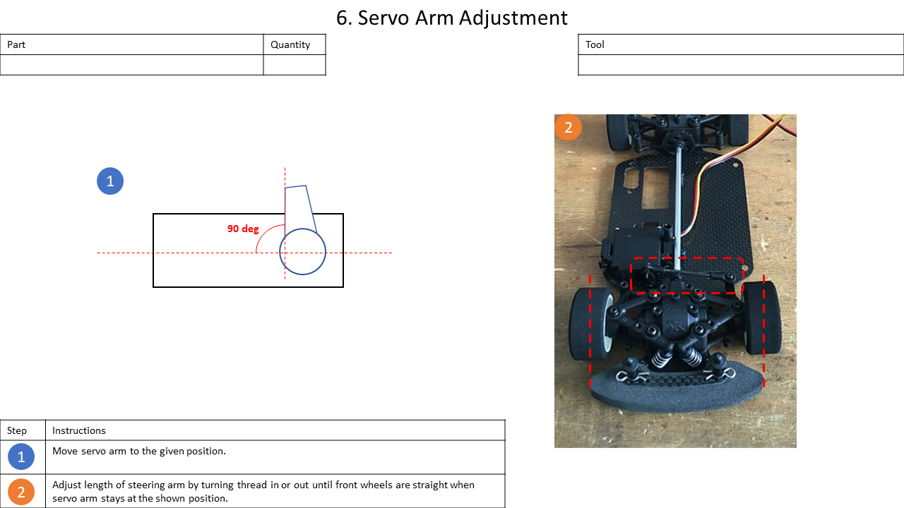
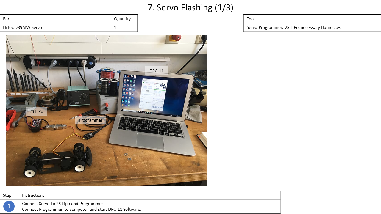
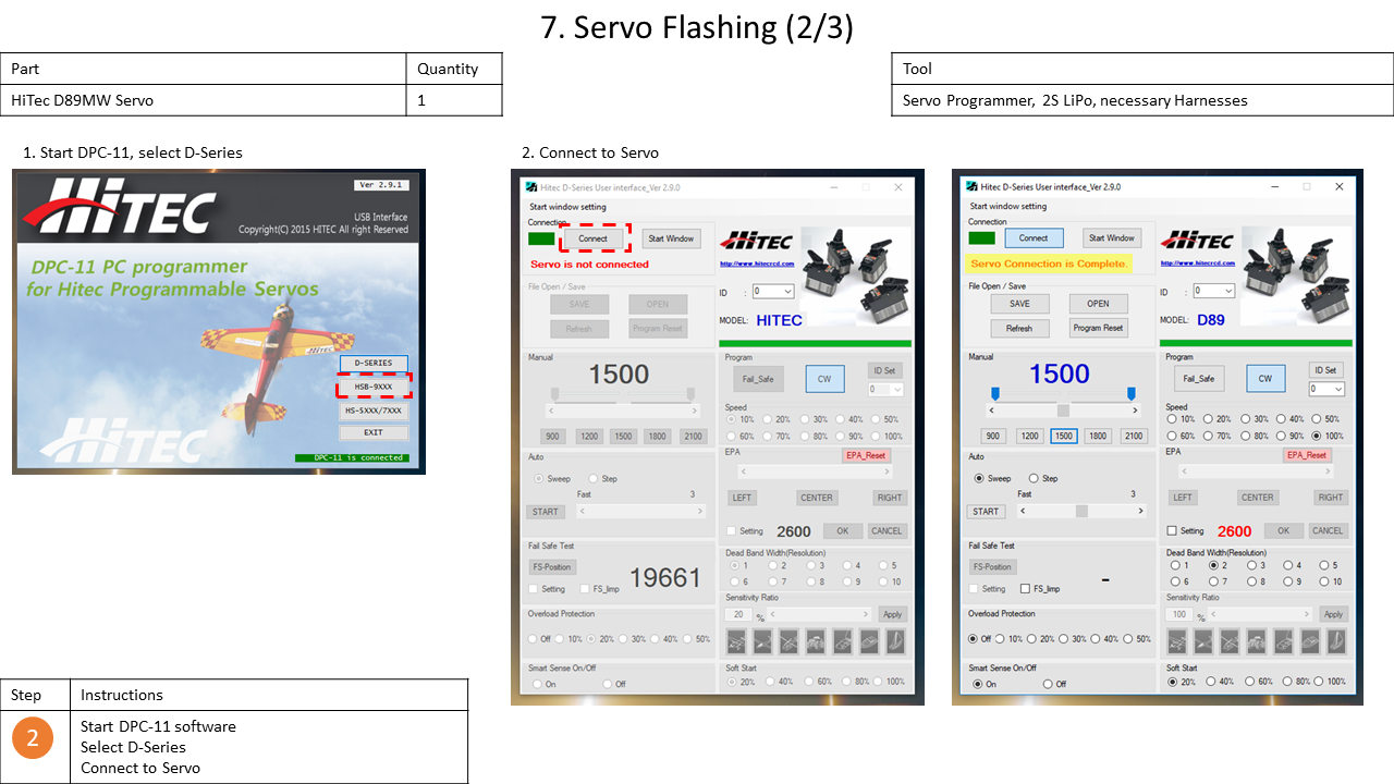
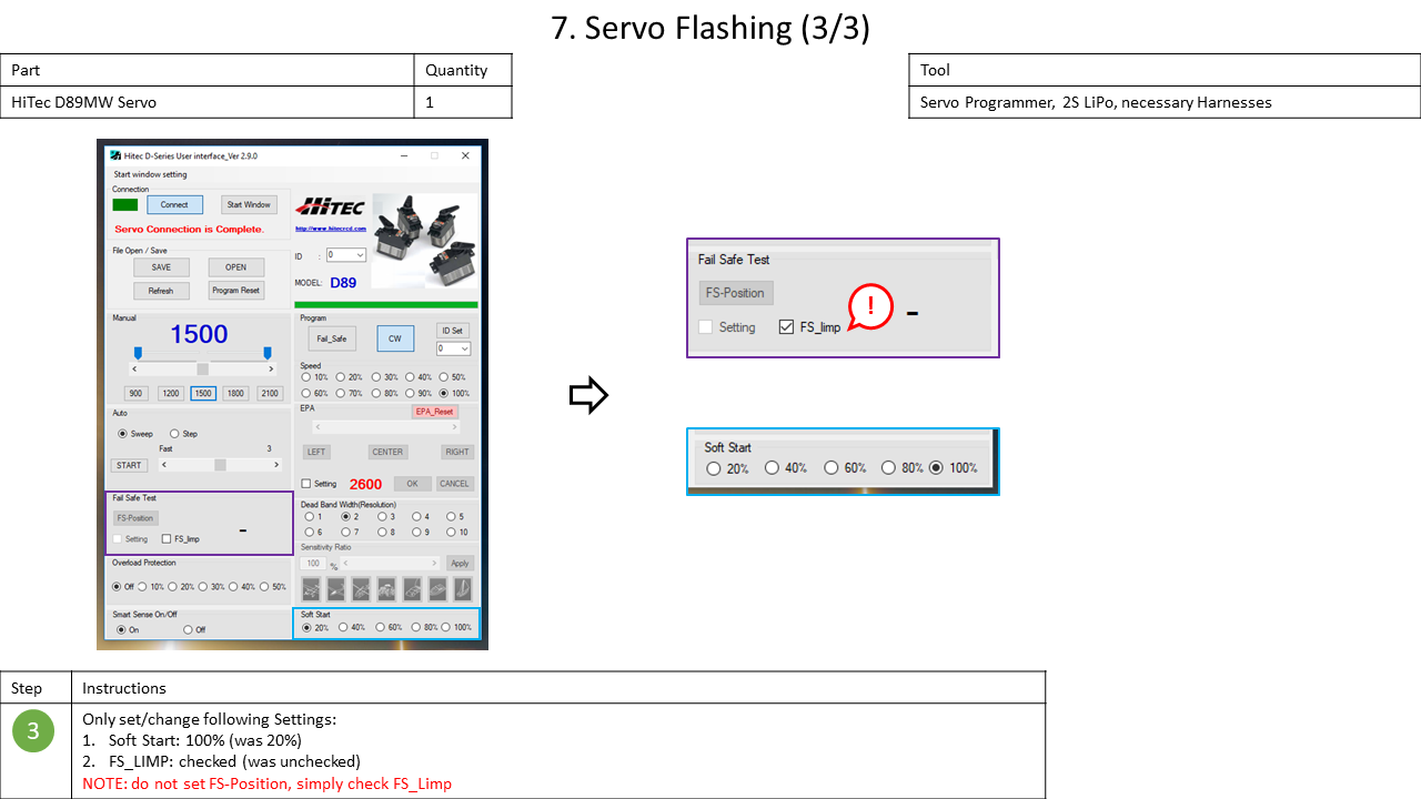
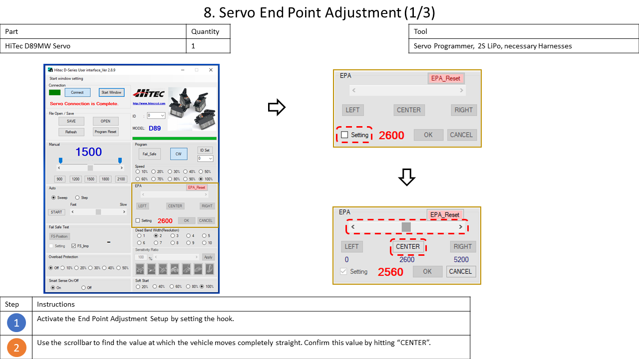
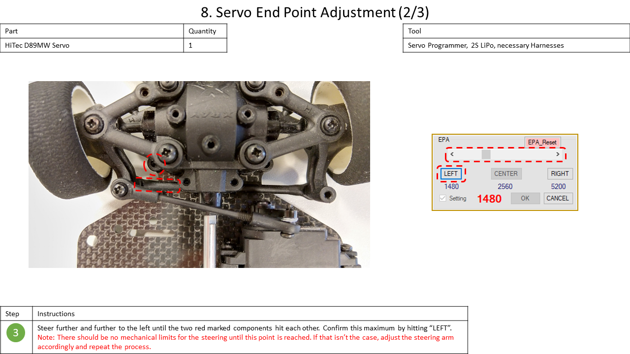
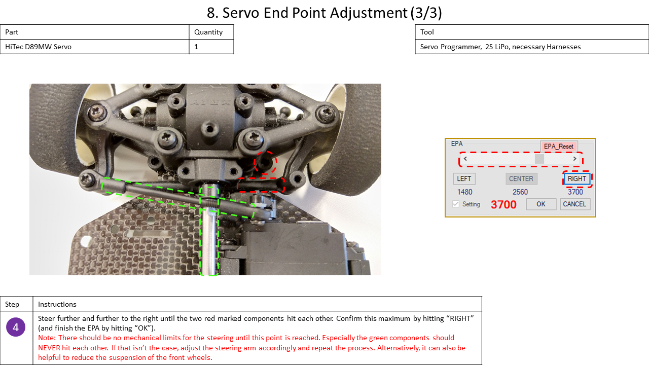
4. Servo Configuration
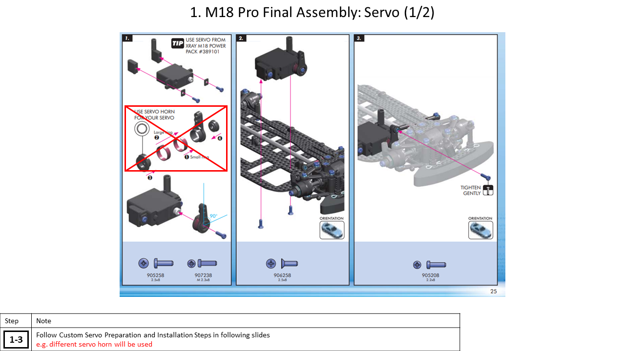
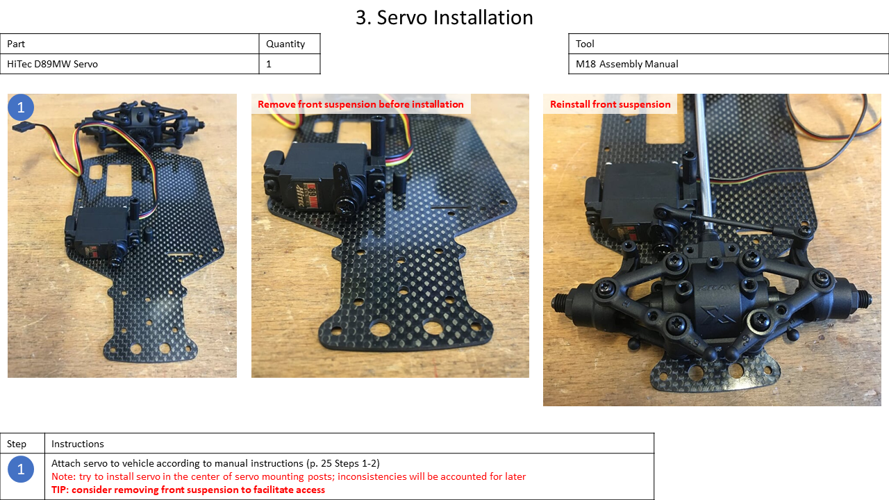
The assembly of the M18 Pro ends with the configuration of the servo and the wheels. In order to configure the HiTEC D89MW Servo, the HiTEC DPC-11 software is used. For the current configuration of all vehicle's servos look here.


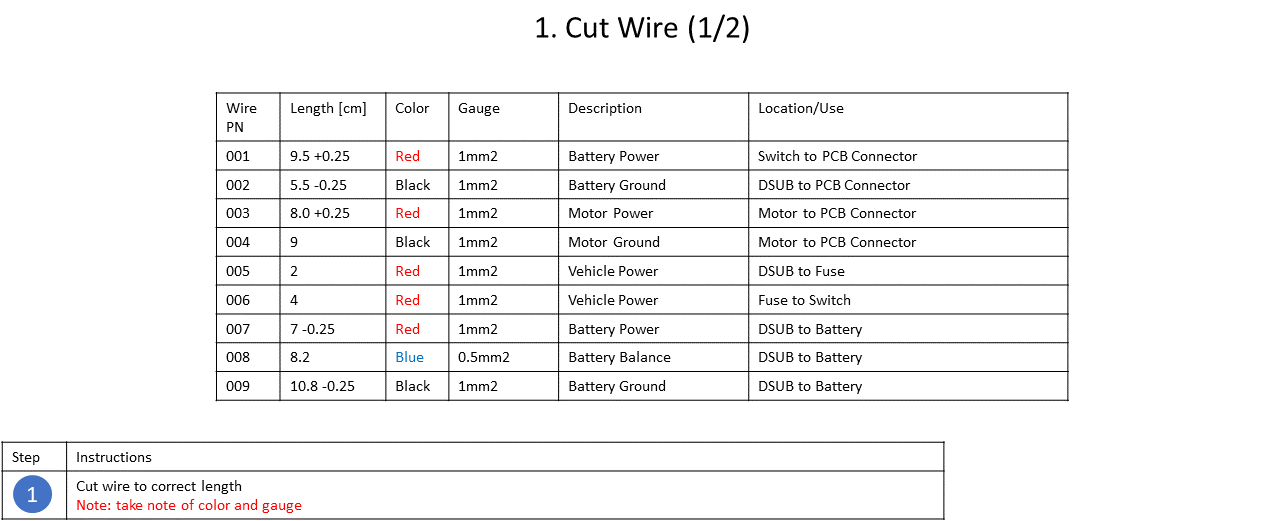
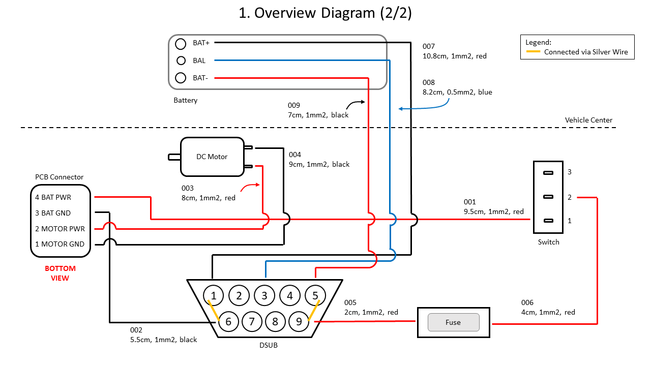
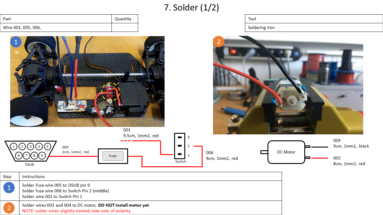
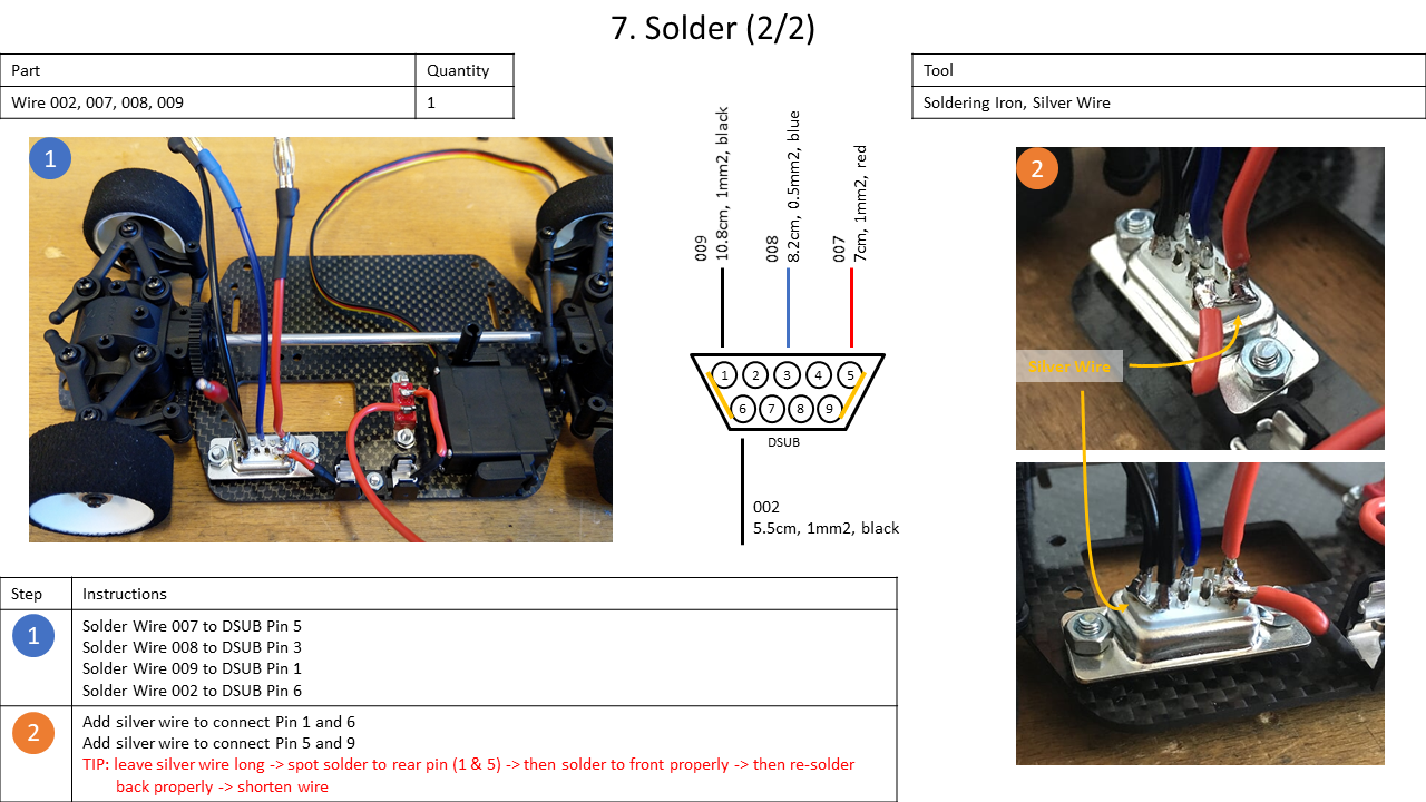
5. Soldering
This section describes the mounting of most electrical components, i.e., the soldering and mounting of
- the motor,
- the fuse,
- the switch,
- the charging connection (DSUB), and
- the battery.
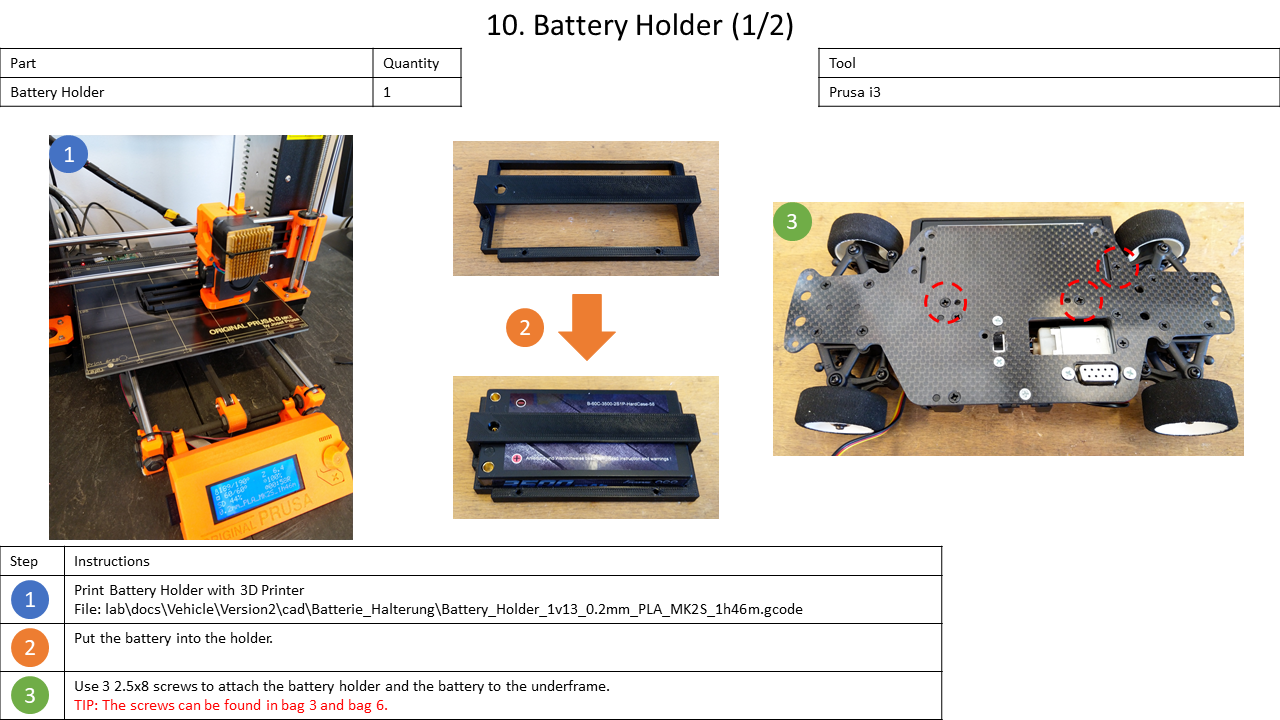
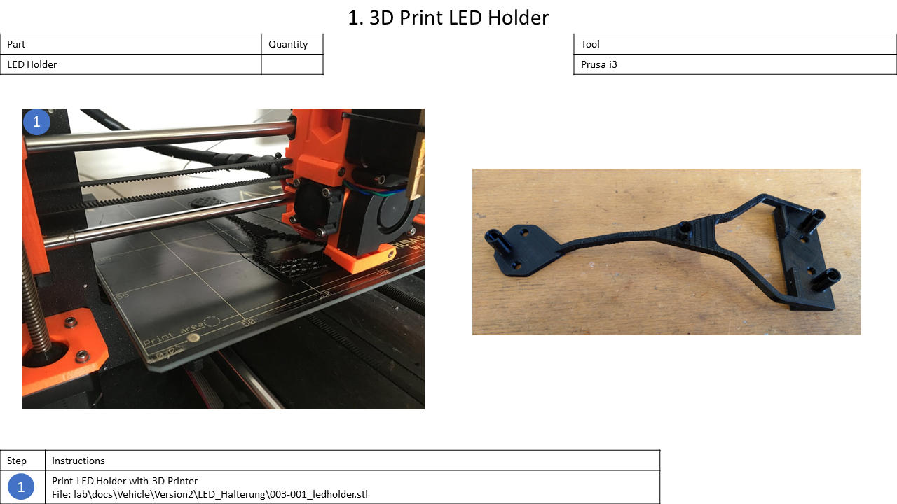
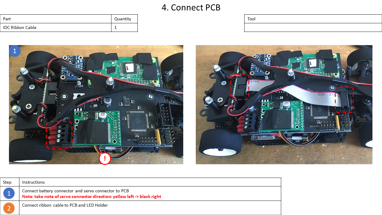
7. Final Assembly
In this last section, the Main Board and the LED Holder will be attached and wired to the chassis. If the Main Board is not soldered yet, see here.
Overview
Content Tools