The Low Level Controller is based on the ATmega2560 microcontroller. Its sole purpose is to act as the interface between the physical and the digital world.
Communication (SPI Slave)
The LLC / ATmega2560 acts as a SPI slave to the MLC / Raspberry Pi. See Mid Level Controller, SPI for details.
Inputs / Sensors
ADC
The ADC measures the battery voltage and the motor current. These are only used for monitoring, not control.
IMU
The yaw rate and acceleration vector are read from the IMU via I2C.
Odometer
The odometer has 3 digital outputs. Each signal change (rising or falling) is handled by an interrupt. The signal change indicates a motor rotation of approx. 60 degrees. The rotation count and motor speed are derived from those signals.
Outputs / Controls
Servo
The servo is controlled through a standard 50 Hz PWM signal, where the signal is encoded in the ON-time, from 1000 us to 2000 us.
Motor
The motor is controlled by a PWM H-bridge at 20 kHz.
LEDs
The four LEDs are individually controlled through GPIO pins.
Watchdog
Should the communication with the MLC fail repeatedly, the LLC will enter a safe mode. The motor is commanded to brake. The safe mode is indicated by flashing all LEDs.
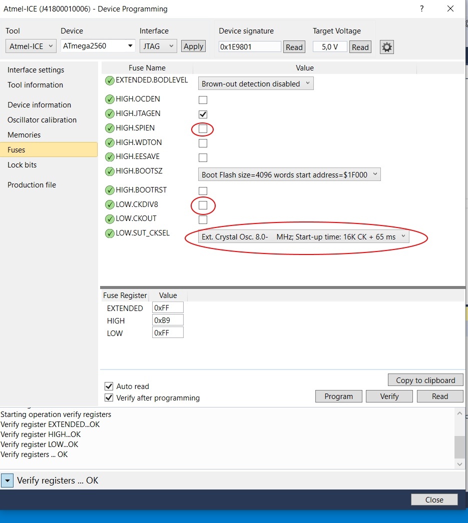
Device Programming, Fuses
When programming the ATmega for the first time, the following fuses must be changed.
Tests
By setting a jumper, a test mode is activated. This allows testing the inputs and outputs without the MLC.
Overview
Content Tools