Page History
...
The outer three LEDs indicate the vehicle pose and are permanently illuminated. The section Pose Calibration describes how the LED positions are related to the reference pose.
...
While the IPS is running, the vehicle is placed in various poses on the floor, following a particular calibration sequence. The calibration features (back_x, back_y, direction_x, direction_y) are recorded from the running IPS. A linear calibration is then fitted using least squares.
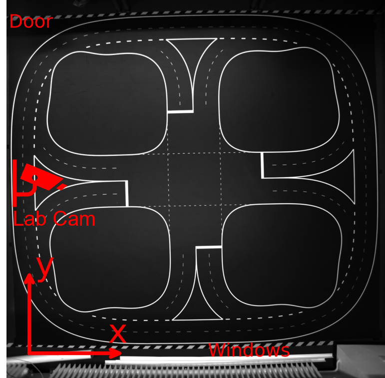
Coordinate Systems
IPS Image Coordinates
The image coordinates correspond to the IPS image sensor pixels. They are only relevant for the IPS LED detection.
Floor Coordinates
| MathJax Inline Equation | ||
|---|---|---|
|
X/Y units: Meter
Yaw unit: Radian
Origin: corner of the PVC canvas, towards the windows on the right.
Yaw angle: Measured from the x-axis, counterclockwise.
Useful yaw equations:
direction_x = cos(yaw)
direction_y = sin(yaw)
yaw = atan2(direction_y, direction_x)
Vehicle Coordinates
X-axis: forwards
Y-axis: left
Origin: center point between both axles.
In practice, this coordinate system is realized with a calibration jig.
Overview
Content Tools