Page History
In this section you can find code examples for a first simple program to test your environment and get familiar with it. This code will let your vehicles drive in a circle (not attached to the map)
The code also includes a possible solution to drive a figure eight in the comments.
Procedure:
- Write your code in C++ or Matlab
- Compile it
- Upload it to the LCC (see here)
- Press "employ"
Source Code explanation:
You define the position of the target points, the speed of your vehicle and the time the vehicle needs to pass a segment. In this example the target points are not connected to the map.
This vector defines the x position of a target point (unitless):
...
This vector defines the y position of a target point (unitless):
...
This vector defines the x speed to the target point. The sign gives the orientation in the cartesian coordinate system (unit m/sec):
vector<double> trajectory_vx = vector<double>{ 0, -1, 0, 1}This vector defines the y speed to the target point. The sign gives the orientation in the cartesian coordinate system (unit (m/sec):
...
C++
Circular trajectory generation for one vehicle
MATLAB
Circular trajectory generation for one vehicleYou find the source code for our examples in the software-folder:
C++
MATLAB
Goal
One single vehicle will drive in a basic circle with a radius of 1m. The center of the circle will be in the center of the map, but the circle will not be connected to the map. The circle shall drive continously.
Initialisation
Define the ID of the vehicle you want to drive. Read the ID in from the LCC using the function cmd_parameter_ints() from our cpm library.
Initialize a DDS Writer for the RTI DDS Service to ensure that position and speed will be sent to the simulation and the vehicle. Write on the topic vehicleCommandTrajectory with datatype VehicleCommandTrajectory. The topic's name is the name of the datatype with a lowercase letter.
Giving direction and speed
Define four points of your circle on a coordinate system.
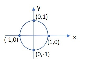
Define the speed vector of the vehicle for each point for the entire trajectory. When you define vx and vy remember that vges = sqrt(vx^2 +vy^2) (as it is a vector). You use this vector to define the direction for your vehicle, so where it has to steer next. Always assign at least a small value to both vectors to ensure the correct direction. Remember that your are defining a physical system, so avoid sharp edges.
Draw the vecotrs on each point of your trajectory:

Now implement your points and speed values using the predefined vetors trajectory_px and trajectory_py for your points of the trajectory and trajectory_vx and trajectory_vy for the speed at each point. The speed is given in m/s. Set the center of the circle to the center of the map at x =2,25m and y= 2m.
Segment duration
For the segment duration keep in mind that speed, time and waylength have to fit. Verify your speed/way/duration with vges =ssegment/tsegmentduration. The segment duration shows the length of a timestep. Transforming it into a timestamp you need to add up all segment durations until the current timestep to the start time:
| MathJax Inline Equation | ||
|---|---|---|
|
Sending the trajectory information to the vehicle
All data are sent to the vehicle using the writer-function from the beginning in the form of
{point_x_position;
point_y_position;
velocity_x_direction;
velocity_y_direction;
timestamp;
}
where each value is a scalar.
Run the example
- Compile your code.
- Select the resulting executable as script the LCC.
- Select vehicle 4 (simulated mode).
- Run the HLC.
- During the experiment, you will see a trail which builds and erases from point to point. This is your trajectory. Now move the simulated vehicle close to the trajectory by dragging it to a close point to the circle trajectory. A second trail will be drawn which is the trajectory for your vehicle to get the circle trajectory.
- Once the vehicle is on the circle trajectory it will drive continously in endless loop.
Matlab specific information
First steps - what the HLC scripts need to include
- Send a ReadySignal message after initialization - only the ID string matters, which must be of the form "
hlc_" + vehicle_id, where the latter is the ID of the vehicle the HLC is responsible for - Wait for the start signal sent by the LCC and propagated to the HLC by the Middleware to start the experiment
- Receive VehicleStateList messages, which include the current states and observations of the vehicle as well as the current time. The history for this signal is set to 1, but you may still get an outdated signal here if you missed a period during your computation and read the next VehicleStateList in the middle of that next period. In that case, it may be better to skip that period as well and wait for the following one to start.
- Send vehicle command messages as a result of the communication including the vehicle ID to the Middleware, which propagates these to the vehicle
- React to stop signals sent by the LCC and propagated to the HLC by the Middleware
- Your function head may differ, but you must use varargin as your last parameter to pass vehicle IDs to your script. This allows you to define, for your script, which vehicle(s) it should be responsible for. Any previous parameters you define are your own 'custom' parameters and need to be specified as additional parameters in the Lab Control Centers' UI before starting your script (if you wish to start it using the UI).
- For eProsima: You must use matlab_domain_id as the parameter before varargin to determine on which domain ID the HLC should communicate with the middleware.
Overview
Content Tools