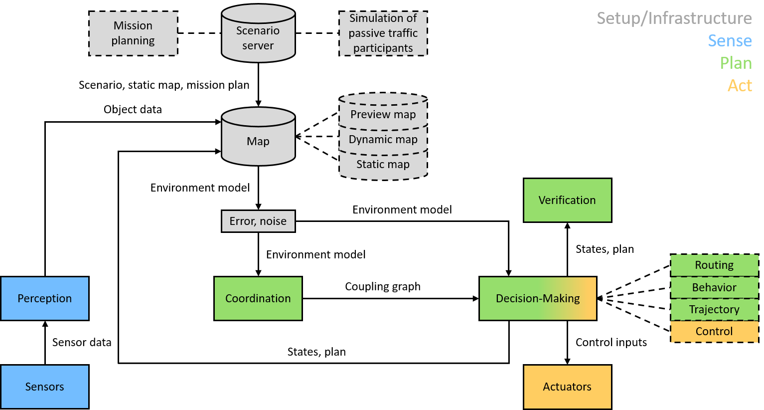
The framework architecture of the CPM Lab follows the Sense, Plan,
Act scheme, including infrastructure functionalities.
Infrastructure
The infrastructure module provides a scenario sever. Scenarios include mission plans and a simulation of passive (non-networked) traffic participants. The scenario data are stored in the map that includes static data like the road network, dynamic data like the positions of traffic participants, and preview data of planning. In order to simulate real environments, the environment model is affected by artificial errors and noises.
Sense
The sense module computes the ID, position, and orientation of each vehicle. The lab camera and four LEDs on each vehicle form the Indoor Positioning System (IPS). The IPS processes images of the vehicles’ LEDs and detects each vehicle’s ID, position, and orientation. A dead reckoning process supports the camera-based system. The dead reckoning process uses data from each vehicle’s Inertial Measurement Unit (IMU) and odometer.
Plan
The planning module includes the submodules coordination, decision-making, and verification. The coordination submodule determines the vehicles’ interaction, stored in a coupling graph. The decision-making submodule plans routs, behaviors, and trajectories. The decision-making performs centralized and distributed computations. The verification submodule verifies the plans to ensure their safety like collision-freedom and to exclude undesirable states like deadlocks.
ACT
The Act module consists of the submodules control and physical actuators. The submodule control uses the planned trajectories as input (reference) and computes corresponding control inputs, i.e., motor voltage and steering angle. The physical actuators of the model-scale vehicles (µCars) execute the resulting control commands using the motor driver and the servo. The control can be computed on the µCars or externally.
High-Level Controller (HLC)
The HLCs run on the computation units (Intel NUCs). Each vehicle has it own HLC. Due to space and weight requirements, we place the computation units outside the vehicles. The HLCs are responsible for coordination, decision-making, and verification. They wirelessly send trajectories to the MLCs and receive fused estimated states of the vehicles from the MLCs. The HLCs exchange data depending on the vehicles’ interaction.
Middleware
The DDS-based middleware runs on the computation units (Intel NUCs) and on the Raspberry Pis. It performs the communications between the HLCs and MLCs and synchronizes their computations.
Mid-Level Controller (MLC)
The MLCs run on the Raspberry Pis, which are mounted on the vehicles. The MLCs receive trajectories from the HLCs and implement trajectory following controllers, which generate torque and steering angle commands and communicate them to the LLCs. The MLCs perform dead reckoning based on measured data of the on-board IMUs and odometers received from the LLCs. They additionally fuse data from the dead reckoning with data from the IPS and communicate them to the HLCs.
Low-Level Controller (LLC)
The LLCs run on the ATmega 2560 microcontrollers, which are mounted on the vehicles. They act as a hardware abstraction layer. The LLCs sample the on-board sensors, convert the sensor signals into data compatible to the MLCs, and then send the sensor data to the MLCs. The LLCs apply the torques and steering angles given by the MLCs to the actuators.
We use a four-layered architecture in the CPM Lab. Each layer is responsible for a separate task, which eases changes in hardware and software.
